16 CI/EDP300-EN Rev. A |
D500
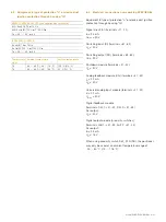
Change from one to two columns
4.2
Cable entry
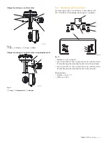
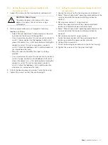
For the cable entry in the housing, there are two tap holes 1/2
- 14 NPT or M20 x 1.5 on the left-hand side of the housing.
One of these holes has a cable gland and the other has a pipe
plug.
M10131
1
2
Fig. 17
1 Pipe plug | 2 Cable gland
4.3
Installing the option modules
IMPORTANT (NOTE)
If you are using the "emergency shutdown
module", there must be a supply voltage of 24 V
DC at ter41 / -42. Otherwise, the
positioner will not be able to function
pneumatically (device in pneumatic safety
position).
IMPORTANT (NOTE)
A functional check of the "emergency shutdown
module" (option) must be performed at least every
2 years. For this purpose, the positioner must
move the valve into the safety position with the 24
V DC signal (ter85 / -86) interrupted.
4.3.1
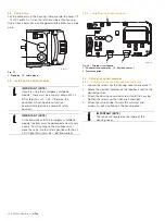
Installing the pressure option
M10144
1
2
3
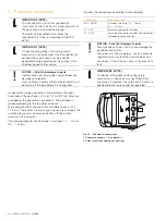
Fig. 18: Printed circuit board
1 I/P converter pneumatics | 2 Position sensor |
3 Pressure option
4.4
Setting the option modules
4.4.1
Setting the mechanical position indicator
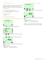
1.
Loosen the screws for the housing cover and remove it.
2.
Rotate the position indicator on the feedback shaft to the
desired position.
3.
Attach the housing cover and screw it onto the housing.
Tighten the screws so that they are hand-tight.
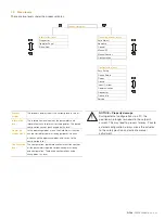
4.
Attach the symbol label to mark the minimum and
maximum valve positions on the housing cover.
IMPORTANT (NOTE)
The labels are located on the inside of the
housing cover.

