33
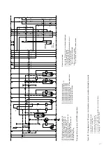
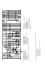
• The five-pole auxiliary switch -S1 is operated by
the charging condition indicator 18. It controls the
charging motor -M0, serves as an electrical inter-
lock for shunt release ON -Y3 when the spring
mechanism is not sufficiently charged, and also
provides an electrical switching readiness signal.
• Operation of the five-pole auxiliary switches
-S3, -S4 and -S5 is dependent on the switching
position of the circuit-breaker.
• Auxiliary switch -S3 interrupts the circuit of the
optional additional shunt release OFF -Y9 with
the circuit-breaker in the open position, and the
circuits of shunt release ON -Y3 and the optional
blocking magnet -Y1 with the circuit-breaker in
the closed position. There is one further NOC for
other purposes.
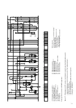
• On failure or absence of the control voltage,
blocking magnet -Y1 mechanically locks the ON
half shaft and simultaneously acts on the corre-
sponding auxiliary switch -S2 to interrupt the
circuit of shunt release ON -Y3.
• Blocking magnet -Y1 is accessible when front
plate 9.2 is removed.
• Auxiliary switch -S4 interrupts the circuit of shunt
release OFF -Y2 with the circuit-breaker in
the open position. One further NOC and three
NCCs are available for annunciation, control and
interlock purposes.
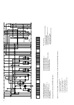
• Auxiliary switch -S5 can be optionally designed
with any possible combination of contacts from
five NOCs to five NCCs. Its contacts are availa-
ble for any required control, annunciation or in-
terlock functions. The auxiliary switch is normally
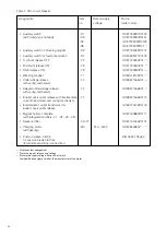
configured as shown in figure 2/15.
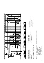
• The single pole auxiliary switch -S7 (fleeting con-
tact time
≥
30 ms) serves to provide a fault signal
("breaker released").
With remote control, the auxiliary switch is
necessarily operated by:
– Shunt release OFF -Y2 or
– Shunt release OFF -Y9 or
– Undervoltage release -Y4 or
– Indirect overcurrent release -Y7.
Note:
1. Shunt releases OFF (-Y2) and ON (-Y3) are ex-
clusively provided for opening and closing in nor-
mal operation. For safety breaking operations,
the second shunt release OFF (-Y9) must be
used, in most cases with a separate control
voltage supply.
These three releases are of the solenoid type
and suitable for a large number of operating
cycles.
2. The undervoltage release (-Y4) and/or indirect
overcurrent release (-Y7) are pure safety and
protection releases and must not be used for
switching in normal operation.
4.3.2
Mounting of the VD4 on trucks from other
manufacturers
VD4 circuit-breakers which are not installed on
ABB withdrawable parts must be fitted with one
or two additional auxiliary switches which are
dependent on the mechanical lock and release
device. These must interrupt the circuit of shunt
release ON -Y3.
Similary to auxiliary switches -S8 and -S9 in Calor
Emag withdrawable parts, no electrial pulse may
arrive during and before mechanical blocking of the
spindle mechanism, and may only be applied again
after the end of mechanical blocking.
This ensures that the shunt release ON cannot be
loaded with an electrical ON pulse when the
withdrawable part is in an intermediate position,
which could burn out the coil.
4.4
Function
4.4.1
Charging of the spring energy storage mechanism
(Figures 4/6, 4/7 and 7/1)
To provide the necessary motive energy, the spring
energy storage mechanism, either charged auto-
matically by a charging motor or manually in a
vertical pumping action with charging lever 19,
depending on the equipment fitted to the circuit-
breaker. The current charging condition is shown at
charging condition indicator 18.
As a precondition for an auto-reclosing sequence,
the operating mechanism is either (re-)charged after
a closing operation automatically by the charging
motor, or it requires (re-)charging by hand if the
operating mechanism is of the manual type.
4.4.2
Closing procedure
(Figures 4/4, 4/6 and 4/7)
The closing process is started by the mechanical
ON push-button 11, or by activation of shunt release
ON -Y3. The release mechanism 31 then permits
drive shaft 30 to be rotated by the (previously)
charged spiral spring. The moving contact 20.3 in
vacuum interrupter 20 is moved until the contacts
touch by cam disk 29 and further kinematic links. In
the further sequence of motion, spring arrangement
25 is tensioned and the appropriate amount of
contact force thus applied. The available overtravel
is higher than the maximum value of contact erosion
during lifetime of the interrupter. During the closing
process, opening springs 27 are simultaneously
tensioned.

