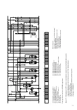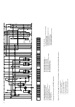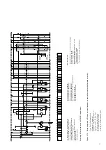
38
7
Commissioning / Operation
7.1
Note on safety at work
• This switchgear may only be operated by
specially trained personnel who are familiar with
the characteristics of the particular device.
• Observe the relevant instructions in section
„Standards and specifications“.
7.2
Preparatory activities
(Prior to application of primary voltage)
• Check the circuit-breaker for any kind of damage
or other injurious environmental influence, and
restore to the proper condition where necessary.
• Remove any contamination, particularly on
insulating parts, which has occurred during
transit, storage or installation.
• Lifting lugs for high current circuit-breakers, if still
fitted, must be removed.
• Check the primary and secondary connections
and the protectiv conductor terminal.
• Check mechanical and electrical interlocks for
effectiveness, without using force.
• Charge the spring energy storage mechanism
by hand (see section „Charging the spring
energy storage mechanism“).
• For test purposes, switch the mechanism on and
off using the mechanical operating elements 11 or
12 (note in this context any specified design
supply voltage and any interlocks installed).
• Check the charging motor on circuit-breakers
with motor-operated mechanisms by applying
supply voltage.
• On motor-driven withdrawable parts, check the
direction of rotation of the travel motors as
described in section „Checking the direction of
rotation of the travel motors ...“.
• For any further questions on the functions of the
withdrawable circuit-breaker part and its testing,
see section „Testing withdrawable parts“.
• Ensure that the Instruction Manual is available to
the operators at all times.
7.3
Movement of the withdrawable breaker part
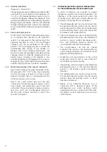
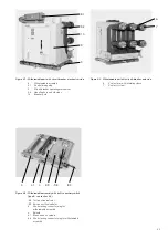
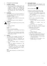
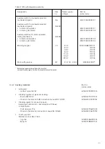
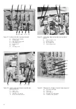
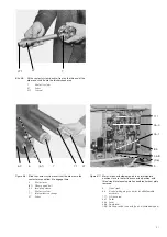
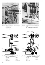
(Figures 4/1, 4/2, 4/3, 7/1 to 7/4)
Perform switching operations with the front doors shut.
7.3.1
Manual insertion from the test/disconnected
position to the service position
• Connect control wiring plug 8.1.
• Close the front door.
• Ensure that the circuit-breaker is in the OFF
position.
• Fit hand crank 5 on square spigot 4.2 of the
spindle mechanism 4.
6
Installation and mounting of the
breaker
Careful and professional installation of the switch-
gear is one of the fundamental conditions of
trouble-free circuit-breaker operation.
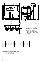
• Install the mechanism enclosure in the panel
without tension or distortion, inserting dished
washers below the nuts or bolt heads at each of
the four mounting points (dependent on the
order).
• Connect the main terminals without any perma-
nent tension or pressure forces, exerted for
example by the conductor bars.
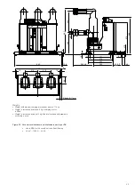
• When connecting the conductor bars, the bolts
must be inserted to the depth shown on the
dimensional drawing.
• Take account of any tested terminal zone.
• Use DIN bolts of tensile class 8.8, fastening
conductor bars together with dished washers.
• Make a short-circuit proof connection between
the PE conductor and the main earthing bar in
the switchgear, using contact washers.
• Remove any dirt. See also section „Servicing“.
Recommended
rated tightening torque
1)
Nm
Lubricant
2)
Thread size
without
Oil
(try)
or grease
M
6 10.5 4.5
M
8
26
10
M 10
50
20
M 12
86
40
M 16
200
80
1)
• Rated tigthening torques for fasteners without Lubrication
are based on the thread friction coefficient 0.14 (the
actual values of which are subject to unavoidable, in some
cases not insignificant, spread).
• Rated tigthening torques for fastener with lubrication in
accordance with DIN 43673.
2)
Thread and contact face of head lubricated.
Take account of any tightening torques which deviate from
the general table (e.g. for contact systems or device
terminals) as stated in the detailed technical documentation.
It is recommended that the threads or head contact surfaces
of the bolts be lightly oiled or greased, so as to achieve a
precisely defined rated tightening torque.

