


17
—
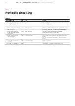
Periodic checking
CAUTION
Before carrying out any operation, make sure
that the operating mechanism springs are
discharged, and that the apparatus is in the
open position.
General
During normal service, the circuit-breakers are
maintenance free.
The frequency and sort of inspections basically depend on
the service conditions. Various factors must be considered:
frequency of operations, interrupted current values, relative
power factor and the installation ambient.
The following paragraph gives the checking program table,
showing the relevant time intervals.
As far as the time interval between these operations is
concerned, it is advisable to comply with the specifications
given in the table, at least during the first check. On the
basis of the results obtained during the periodic
inspections, set the optimal time limits for carrying out the
operations listed in table 2.2 (see page 16).
Table 2.1
Subject of the
inspection
Procedure
Positive check
1
Insulation
resistance
Medium voltage circuits
With a 2500 V megger, measure the insulation resistance between phases
and exposed conductive part of the circuit.
Auxiliary circuits
With a 500 V megger (installed equipment permitting) measure the
insulation resistance between the auxiliary circuits and the exposed
conductive part.
The insulation resistance should be a few MΩ
and, in any case, constant over time.
The insulation resistance should be at least 50
MΩ and, in any case, constant over time.
2
Auxiliary
circuits
Check that the connections to the control circuit are correct; proceed with
relative supply.
Normal switching and signaling.
3
Manual
operating
mechanism
Carry out a few closing and opening operations. N.B. Supply the u/v
release and the locking magnet on the operating mechanism at the relative
rated voltage
The operations and relative signals occur
correctly.
4
Motor
operator*
Supply the geared motor for spring charging at the relative rated voltage.
Carry out a few closing and opening operations. N.B. Supply the
undervoltage release and the locking magnet on the operating mechanism
at the relative rated voltage. (if provided)
The springs are charged correctly. The signals are
correct.
The geared motor cuts off when the springs are
charged.
The geared motor recharges the springs after
each closing operation.
5
Under voltage
release*
Supply the undervoltage release at the relative rated voltage and carry out
the circuit-breaker closing operation. Disconnect the power supply to the
release.
The circuit-breaker closes correctly. The signals
are correct.
The circuit-breaker opens. The signal changes
over.
6
Shunt opening
release and
additional
shunt opening
release*
Close the circuit-breaker.
Supply the shunt opening release at the relative rated voltage.
The circuit-breaker opens correctly. The signals
are correct.
7
Shunt closing
release*
Open the circuit-breaker. Supply the shunt closing release at the relative
rated voltage.
The circuit-breaker closes correctly. The signals
are correct.
8
Key lock*
Open the circuit-breaker Turn the key and remove it
Attempt the circuit-breaker closing operation
Insert the key again and turn it 90°
Carry out the closing operation
Neither manual nor electric closing takes place.
Both electric and manual closing take place
correctly; in this position the key cannot be
removed.
9
Locking
electromagnet
(RL1)*
With the circuit-breaker open, springs charged and locking electromagnet
not supplied, attempt to close the circuit-breaker both manually and
electrically.
Closing is not possible.
10
Auxiliary
contacts in the
operating
mechanism
Insert the auxiliary contacts into suitable signaling circuits. Carry out a few
closing and opening operations.
Signals occur correctly.
11
Racking device
with lever on
the unit
With closed circuit-breaker try to operate the lever.
The lever cannot be operated and the racking-out
are not possible.
Summary of Contents for VD4 Series
Page 23: ......


