background image

— 

A B B MOTION DR I V ES US - CONNEC TI V IT Y 

VFD-GATEWAY 

EtherNet/IP™ to Modbus RTU gateway User Manual

Summary of Contents for VFD-GATEWAY

Page 1: ... ABB MOTION DRIVES US CONNECTIVIT Y VFD GATEWAY EtherNet IP to Modbus RTU gateway User Manual ...

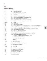
Page 2: ...LVD EOMU02U EN REVB 04 2022 VFD GATEWAY EtherNet IP User Manual Table of contents 1 Safety Instructions 2 Installation 3 Setup 5 Appendix 4 Troubleshooting ...

Page 3: ...ameters ACS880 and DCS880 13 3 5 Setup data mapping and typical parameters ACH580 E Clipse 14 3 6 ABB drives control profile 15 3 7 Ethernet configuration settings 15 19 3 8 Ethernet IP scanner setup 20 22 3 9 Configuring the VFD GATEWAY Web browser interface 23 3 10 Additional screens and settings 23 Changing the VFD GATEWAY ADMIN password 24 Modbus RTU configuration 25 VFD GATEWAY data tables 26...

Page 4: ... to make sure that there are no parts under voltage in reach The impedance of the multimeter must be at least 1 Mohm Avoidance of electrostatic discharges VFD GATEWAY devices and equipment are sensitive to electrostatic discharge which can cause internal damage and affect normal operation Observe the following rules when handling the VFD GATEWAY Touch a grounded object to discharge potential stati...

Page 5: ...showing how to mount the device and where the power communications connections are made 2 1 Mounting the VFD GATEWAY DIN rail according to DIN EN 50022 35 mm depth 7 5 mm or 15 mm Mounting with screws M3 see Appendix for hole fixing dimensions Note TA543 option not included is ordered separately from the VFD GATEWAY Fastening torque 1 2 Nm ...

Page 6: ...al safety of VFD GATEWAY extra low voltage circuits 24 V DC supply communication interfaces I O circuits and all connected devices must be powered from sources meeting requirements of SELV PELV class 2 limited voltage or limited power according to applicable standards 2 3 Ethernet interface Connect your Ethernet interface via the VFD GATEWAY RJ45 jack Note EtherNet cable not included The network c...

Page 7: ...lt in Bus Termination and Pull Up Pull down resistors When yellow lights are lit bus termination resistor is activated or the pull up pull down resistors are activated The Modbus RTU can be connected to up to 5 ABB drives via the following connections Terminating resistors 120 Ω W is required at both line ends of the Modbus RTU network The VFD GATEWAY has Built in 120 Ω resistor that is enabled fr...

Page 8: ...he Modbus module on the gateway needs to be removed using the following instructions Ensure the VFD GATEWAY is turned off Press the tab on the side of the module and pull up on the module to remove it from the VFD GATEWAY After it is removed turn the top dip switches off They are currently in the on position from the factory Flip the switches to the left for OFF towards the ABB logo and reinstall ...

Page 9: ... For best immunity ABB recommends high quality cable Keep the cable as short as possible Avoid unnecessary loops and parallel runs near power cables such as motor cables BUS Cable Transmission rate 38 4 kbit s Construction 2 cores twisted with common shield Conductor cross section 0 22 mm 24 AWG Twisting rate 10 per meter symmetrically twisted Core insulation Polyethylene PE Resistance per core 10...

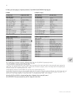
Page 10: ... Min 0 Hz 11 05 Ref 1 Max 60 Hz 98 02 Comm Protocol Select STD Modbus 53 02 Station ID Drive 1 2 up to 5 53 03 Baud Rate 38 4 kbps 53 04 Parity 8 EVEN 1 ACS355 typical parameters READ from VFD Fixed word 4 Status Word 53 10 EFB Par 10 104 Motor Current 53 11 EFB Par 11 107 DC Bus Voltage 53 12 EFB Par 12 106 Motor Power 53 13 EFB Par 13 110 Drive Temp 53 14 EFB Par 14 1202 Constant Speed 1 53 15 E...

Page 11: ...elays to the data The VFD GATEWAY only supports these default settings For ACH Q S580 the write data starts at 58 108 and First 7 registers must be reads 58 101 58 107 Note You MUST set 58 06 to refresh settings after all parameters in group 58 are set ACS380 ACQ S580 typical parameters READ from VFD 58 101 Data I O 1 Status Word 16 bit 58 102 Data I O 2 Act 1 16 bit 58 103 Data I O 3 Act 2 16 bit...

Page 12: ...Data I O 10 1 06 Output Frequency 58 111 Data I O 11 1 31 Ambient Temperature 58 112 Data I O 12 47 21 Data Storage Write to VFD 58 113 Data I O 13 Control Word 16 bit 58 114 Data I O 14 Ref 1 16 bit 58 115 Data I O 15 Ref 2 16 bit 58 116 Data I O 16 47 21 Data Storage 58 117 Data I O 17 47 22 Data Storage 58 118 Data I O 18 47 23 Data Storage 58 119 Data I O 19 47 24 Data Storage 58 12 Data I O 2...

Page 13: ...t frequency 3 output frequency 4 9 E Clipse parameters 58 107 58 112 settings Note You MUST set 58 06 to refresh settings after all parameters in group 58 are set Note ACH580 E Clipse power must be cycled for changes to take effect ACH580 E Clipse typical parameters READ from VFD Fixed word 4 Status Word Fixed word 5 Speed or Freq Fixed word 6 Speed or Freq 58 107 Data I O 7 107 Motor Current 107 ...

Page 14: ...0 DCS880 and ACH580 E Clips The speed scaling is 20000 1 For Vector Mode Parameter 46 01 needs to be set to the rpm of max speed 2 For Scalar Mode Parameter 46 02 needs to be set for max Speed Scaling ACS355 The speed scaling is 20000 1 Scaling is set in 11 03 and 11 04 ABB Drives profile Control Word Bit structure Byte Bit 7 Bit 6 Bit 5 Bit 4 Bit 3 Bit 2 Bit 1 Bit 0 0 Reset Ramp in Zero Ramp Hold...

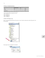
Page 15: ...egers 0 14 Drive 2 Integer 15 29 Drive 3 Integer 30 44 Drive 4 Integer 45 59 Drive 5 Integer 60 74 3 8 Ethernet IP scanner setup Step 1 In the project find the Ethernet Connection in your controller configuration that will be used for the VFD GATEWAY Step 2 Right click on it and select New Module Assembly Instance Size Input 101 75 16 bit Output 100 75 16 bit Configuration 1 0 8 bit ...

Page 16: ... Ethernet Module and hit create Note Use either EDS File or Generic module DO NOT USE BOTH Step 4 Next populate the required generic module fields per below and press OK Name Example VFD_Gateway Comm Format Data INT IP address default of gateway is 192 168 0 10 Input Instance Assembly 101 Size 75 Output Instance Assembly 100 Size 75 Configuration 1 Size 0 ...

Page 17: ...PLC software to be se lected Note the EDS file MUST be installed through EDS hardware installation tool before it is available to use Note Use either EDS File or Generic module DO NOT USE BOTH Step 6 On the next screen give the module a name and enter the VFD GATEWAY s IP address Default is 192 168 0 10 This can be changed from the web page setup ...

Page 18: ...8 After change is selected the following screen will appear Select INT and press OK This will create 75 integers in out Drives Input Output data array mapping is as follows Drive 1 Integers 0 14 Drive 2 Integer 15 29 Drive 3 Integer 30 44 Drive 4 Integer 45 59 Drive 5 Integer 60 74 ...

Page 19: ...LVD EOMU02U EN REVB 04 2022 19 The data registers that are not used will be just blank data as a place holder ...

Page 20: ...4VDC power 2 From the web interface device Laptop PC open a web browser window and navigate to the default IP address 192 168 0 10 255 255 255 0 3 The VFD GATEWAY will navigate to the main page of the setup interface Supported web browsers HTML5 capable web browsers supported by most modern browsers If the IP address is unknown see the appendix Discover or Reset IP address Step 2 Open the settings...

Page 21: ...teway will check for a loss of connection with a Node drive on the Modbus RTU network Example if the value is programmed to 3 seconds and node drive is powered down the gateway will check every 3 seconds for this node drive A lower setting will decrease the update speed of the VFD Gateway when there is a problem with the Modbus RTU network The Ethernet IP Address Subnet Mask and the Gateway inform...

Page 22: ...hen 2 Apply setting button The VFD GATEWAY will perform a restart communication will be lost and the web interface will need to be reconnected with the new IP address Note Confirm the updated settings have been updated by navigating back to the settings screen Note The Modbus RTU setting are not User programmable 1 2 ...

Page 23: ...he VFD GATEWAY ADMIN password Step 1 From the settings Screen Login as the ADMIN user Step 2 Enter Username ADMIN Default Password ADMIN click OK Step 3 Click Change Password Step 4 The password change box will prompt you to enter the existing password and the new password twice ...

Page 24: ...n Modbus RTU settings can be found on the Setting screen Note The Modbus RTU settings can t be changed The Settings screen shows the Active Ethernet IP settings and the Active Modbus Settings Note The Standard User can only view the settings from this page ...

Page 25: ... Modbus Node Selected in the Settings Screen will be shown above the Data table The Actual Gateway Drive Data being transferred from the VFD to the Ether net IP Network Read Data and the Ethernet IP network to VFD Write Data is displayed in the tables Data is shown in Decimal and is Read Only Each of the five drives can be selected by clicking on the corresponding drive number at the top of the sc...

Page 26: ...rm screen shows any Communication errors on each of the Ethernet IP or Modbus Drive Nodes The VFD Gateway Alarms can be represented in the following Output Lights The wiring shown is optional each output has a status LED built into the VFD GATEWAY ...

Page 27: ...re 1 Power down the VFD GATEWAY 2 Connect 24VDC to Terminal 2 and 3 and connect the 0VDC to Terminal 1 3 Power up the VFD GATEWAY 4 When output terminal lights 14 through 21 are lit the VFD GATEWAY power can be removed 5 When the VFD GATEWAY is powered down remove the connections from terminal 2 and 3 6 Power up the VFD GATEWAY The following will be reset VFD Gateway web password to be verified Et...

Page 28: ...7 Communication Diagnostics refer to the Drive manuals in each case 58 08 Receive and 58 09 transmit ACS355 look at 53 06 OK Messages Use the Data screen in the VFD to see if we are transmitting data Drive Communicating but not running Check Start Stop Speed Reference refer to drive set up page for all drives Make sure the control device is sending the correct information see ABB State Machine ref...

Page 29: ...in mm W1 in mm W2 in mm D1 in mm D2 in mm X in mm X1 in mm 5 63 143 1 3 23 82 2 84 72 1 5 31 135 3 07 78 1 45 37 2 24 57 2 04 52 0 17 4 25 0 16 4 Allow a minimum of 0 79 in 20mm clearance on all sides This provides ventilation and electrical isolation It is recommended to mount the modules on an earthed mounting plate or an earthed DIN rail independent of the mounting location Horizontal mounting ...

Page 30: ...CS380 Firmware Manual 3AXD50000027600 ACH580 Firmware Manual 3AXD50000611058 ACQ580 Firmware Manual 3AXD0000016097 ACS580 Firmware Manual 3AUA0000085967 ACS880 Firmware Manual Primary Control Program 3ADW000474R0301 DCS880 Firmware Manual 3AXD50000289554 ACH580 E Clipse User Manual LED State Color LED ON LED OFF LED Flashing PWR Power supply Green Power supply present Power supply missing MC Micro...

Page 31: ...are not supported Cable type CAT5 or higher and type UTP FTP or STP Serial interface Serial standard RS 485 Modbus RTU Baudrate 38 400 bps Data bits 8 Parity Even Stop bits 1 Terminator for RS 485 120 ohms watt Built In Isolation 2kV Built In Serial signals RS 485 2 wire No of drive connections Up to 5 max ABB Drives supported ACS355 limited support ACH580 E Clipse limited support ACS180 ACS380 AC...

Page 32: ...the agreed particulars shall prevail ABB does not accept any responsibility whatsoever for potential errors or possible lack of information in this document We reserve all rights in this document and in the subject matter and illustrations contained therein Any reproduction disclosure to third parties or utilization of its contents in whole or in parts is forbidden without prior written consent of...

Reviews: