Page 3
© 2023 ABB. All rights reserved.
BDFB Gateway_QSG
Rev. 2.0
QUICK START GUIDE
Front Panel
H569445 G101 & G102
Step R1
-
Remove Existing Panel and Mount Gateway Assembly
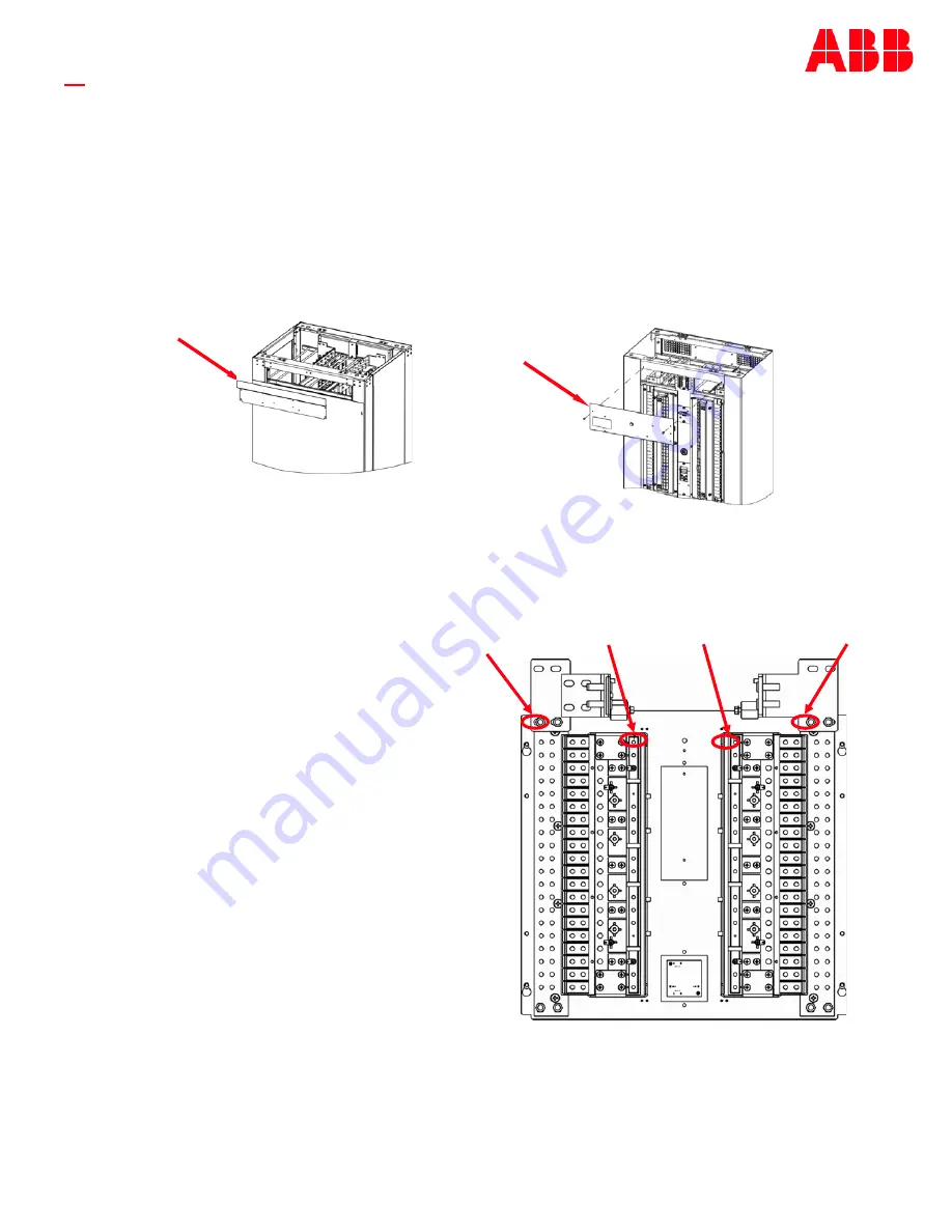
Gateway assembly replaces a blank panel at the top of the BDFB:
H569445 G101 & G102
-
Top Rear
H569445 G7 & G8
-
Top Front
1. Remove existing panel by removing screws: rear panel
-
4 screws , front panel
-
2 screws. Save the hardware.
2. Mount Gateway assembly to chassis with the card on the inside of the panel: rear panel lip is top, front panel lip is on
the bottom. Secure with screws removed in 1. Torque to 2.8Nm (25 in
-
lb)
-
5/16”
socket.
H569445 G7 & G8
Rear Panel
Step R2
-
Install Gateway Power Cables
Note: Follow all safe and appropriate installation practices when performing this work on a live system.
Rear mounted Gateway assembly
-
You will need to remove the protective cover of the Gateway kit to be able to
access its ports (four screws).
1. Remove the top BDFB rear access panel.
2. Verify polarity of bus bars with a meter
before making connections.
3. Remove the protective cover of the Gateway
kit ( rear panel only)
-
four screws.
4. Connect the Gateway card to BDFB power using
the 850048025 wire set provided with the kit:
a) If connection points shown at right have Faston blades
replace the ring terminals of the wire set with Faston
terminals (provided).
b) Attach the wire set terminals A1 (+), A1
(
–
),
B1 (+), and B1
(
–
)
to the DC bus bars .
Use the provided hardware.
Torque ring terminal screws to 65 in
-
lb if present.
a) Attach the other end of the cable assembly to the power
connector
J9
located on the bottom right hand side of the Gateway card (see Wiring Diagram).
5. Route power and as desired using cable ties.
Rear mounted Gateway Assembly: route the cables along the bracket connecting the front and back of the BDFB to keep
them out of the path of the load wires.
6. Replace the top BDFB rear access panel.
(Red) B1 (+)
(Red) A1 (+)
(Black) A1 (
-
)
(Black) B1 (
-
)
BDFB Rear View
Install Gateway Assembly—R steps


