42
VM1
- USER MANUAL
—
9. Installation
9.6. Power circuit connections of
fixed circuit breakers
9.6.1. General recommendations
•
Select the cross-section of the conductors
according to the service current and the short-
circuit current of the installation.
•
Prepare special post insulators, near the terminals
of the fixed circuit breaker or enclosure, sized
according to the electrodynamic forces deriving
from the short-circuit current of the installation.
9.6.2. Assembly of the connections
•
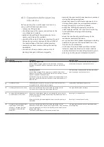
Check that the contact surfaces of the
connections are flat, and are free of any burrs,
traces of oxidation or deformation caused by
drilling or impacts received.
•
According to the conductor material and the
surface treatment used, carry out the operations
indicated in table T1 on the contact surface of the
conductor.
T2
Bolt
Recommended tightening torque (
1
)
(
1
) The nominal tightening torque is based on a friction coefficient of the thread of 0.14
(distributed value the thread is subjected to which, in some cases, is not negligible).
The nominal tightening torque with lubricant is according to the DIN 43673
Standards.
(
2
) Oil or grease. The thread and surfaces in contact with the lubricated heads.
Take into account the deviations from the general Standards table (for example, for
contact systems or terminals) as foreseen in the specific technical documentation.
The thread and surfaces in contact with the heads of bolts must be slightly oiled or
greased, so as to obtain a correct nominal tightening torque.
Without lubricant
With lubricant (
2
)
M6
10.5 Nm
4.5 Nm
M8
26 Nm
10 Nm
M10
50 Nm
20 Nm
M12
86 Nm
40 Nm
M16
200 Nm
80 Nm
T1
Bare copper
Copper or silver-plated aluminium
Bare aluminium
•
Clean with a fine file or
emery cloth.
•
Tighten fully and cover the
contact surfaces with 5RX
Moly type grease.
•
Clean with a rough dry cloth.
•
Only in the case of obstinate traces of
oxidation, clean with a very fine grain
emery cloth taking care not to remove
the surface layer.
•
If necessary, restore the surface
treatment.
•
Clean with a metal brush or emery cloth.
•
Cover the contact surfaces again immediately with
neutral grease.
•
Insert the copper-aluminium bimetal with surfaces
shined (copper side in contact with the terminal;
aluminium side in contact with the connection)
between the aluminium connection and the copper
terminal.
Assembly procedures
•
Put the connections in contact with the circuit
breaker terminals taking care to avoid mechanical
stresses (traction / compression) on, for example,
the conducting busbars on the terminals.
•
Interpose a spring washer and a flat washer
between the head of the bolt and the connection.
•
It is advisable to use bolts according to DIN class
8.8 Standards, also referring to what is indicated
in table T2.
•
In the case of cable connections, strictly follow the
manufacturer’s instructions for making the
terminals.
Summary of Contents for VM1
Page 59: ...MEDIUM VOLTAGE PRODUCTS 59 59 ...

