1
2
1
M ED I U M VO LTAG E P R O D U C T S
43
43
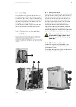
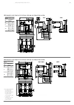
Fig. 15
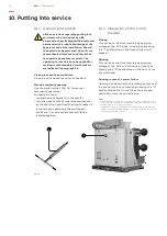
9.7. Earthing
For the fixed version circuit breaker, carry out
earthing by means of the special screw marked
with the relative symbol. Clean and degrease the
area around the screw to a diameter of about 30
mm and, on completion of assembly, cover the
joint again with vaseline grease.
Use a conductor (busbar or braid) with a cross-
section conforming to the Standards in force.
9.8. Connection of the auxiliary
circuits
Note: the minimum cross-section of the wires used for the auxiliary
circuits must not be less than the one used for the internal cabling.
Furthermore, they must be insulated for 3 kV test.
It must also be remembered that the auxiliary circuit must be checked at
the maximum voltage of 2 kV in accordance with the prescriptions of the
standards.
Fig. 14
9.8.1. Fixed circuit breaker
Connection of the circuit breaker auxiliary circuits
must be made by means of the terminal boxes (1)
(fig. 14) mounted inside the circuit breaker and
the wires must pass through the connector (2).
Outside the connector, the cables must pass
through a suitable metal protective cover (pipe,
wiring duct, etc.) which must be earthed.
To avoid the cabling wires outside the circuit
breaker (provided by the customer) accidentally
coming into contact with moving parts and
therefore damaging the insulation, it is advisable to
position and fix the wires as shown in the figure.
Before removing the drive cover to access
the terminal box, check that the circuit
breaker is open with the closing springs
discharged.
9.8.2. Withdrawable circuit breakers
The auxiliary circuits of withdrawable circuit
breakers are fully cabled in the factory as far as
the connector (fig. 15).
For the external connections, refer to the electric
wiring diagram of the switchgear.
Summary of Contents for VM1
Page 59: ...MEDIUM VOLTAGE PRODUCTS 59 59 ...

