background image

M ED I U M  VO LTAG E  P R O D U C T S

55

55

11.1.3.   Procedure for discharging the capacitor/s

Activate the circuit breaker.
Disconnect the power supply voltage.
Operate the circuit breaker by pressing the 
pushbuttons with the following cycle: O-C-O.
The luminous “Ready” signal turns off when the 
operation cycle has been completed, i.e. when the 
circuit breaker is no longer ready for operations.
After 8 minutes have passed, the capacitor 
voltage drops to a value of less than 15 V.
If required in specific cases, further information 
can be obtained from the technical 
documentation regarding the switching apparatus 
(e.g. any special service conditions agreed on), as 
well as from this instruction manual.

11.1.4. Drive with magnetic actuator

The drive with magnetic actuator is maintenance-
free up to the number of operation cycles 
indicated in paragraph 11.1.1.

11.2.  Inspections and functional 

tests

11.2.1.   Interruption devices in general 

• 

Carry out regular inspections to check that the 
interruption devices are in good condition.

• 

Inspection at fixed intervals can be waived when 
the apparatus is permanently monitored by 
qualified personnel.

• 

Above all, the checks must include a visual 
inspection to check for any contamination, traces 
of corrosion and electrical discharge phenomena.

• 

Carry out more frequent inspections when there 
are unusual operating conditions (including 
adverse climatic conditions) and in the case of 
environmental pollution (e.g. heavy contamination 
or an atmosphere with aggressive agents).

• 

Visual examination of the isolating contacts. 
Turning the system of contacts alternately is 
recommended, in order to keep the internal 
surface of the contact areas clean. The contact 
areas must be cleaned if there are signs of 
overheating (discoloured surface) (also see the 
paragraph on “Repairs”).

• 

If any anomalous conditions are found, 
appropriate servicing measures must be taken 
(see the paragraph on “Servicing).

11.2.2.  Circuit breaker pole

No check is required apart from what has already 
been specified in par. 10.3.

11.3.  Servicing

11.3.1.   Interruption devices in general

If cleaning is found to be necessary during the 
inspections, as specified in par. 10.3., use the 
following procedure:

• 

insulate the working area and make it safe by 
following the safety regulations specified in the 
IEC/DIN VDE Standards.

• 

general cleaning of the surfaces:

 - dry and eliminate any light deposits of dirt using 

a soft dry cloth;

 - more resistant deposits of dirt can be removed 

using a slightly alkaline household cleanser or 
Rivolta BWR 210 type detergent.

• 

cleaning the insulating surfaces and conductive 
components:

 - light dirt: with Rivolta BWR 210 detergent;
 - resistant dirt: with cold 716 type detergent.

After cleaning, rinse thoroughly with clean water 
and dry carefully

Note

Only use halogen-free detergents and never trichloroethane, 
trichloroethylene or carbon tetrachloride!

11.3.2.   Actuator and transmission system

A functional test of the drive must be carried out:

• 

when the number the number of operating cycles 
indicated has been exceeded, or 

• 

during maintenance operations.

Before carrying out the functional test, open the 
circuit breaker and 

• 

take it to the test position (withdrawable circuit 
breaker) or 

• 

insulate the working area and make it safe in 
conformity with the safety rules and according to 
the regulations in force (fixed circuit breakers)

• 

follow the procedure for discharging the capacitor

• 

carry out a visual inspection of the state (removing 
the front panel), e.g. of:

 - lubrication of the ball bearings
 - the operation counter
 - assembly of the sensors
 - the position indicator.

Functional test:

• 

Connect the power supply voltage.

• 

Carry out several no-load operations. This test 
particularly applies to circuit breakers which are 
rarely activated under normal conditions.   
To check the capacitor, carry out a rapid O-C-O 
cycle of operations of the circuit breaker, by 
pressing the pushbuttons on the front of the 
circuit breaker in rapid succession.

• 

The LEDs on the inductive sensors are activated as 
soon as the circuit breaker has reached the closing 
and opening limit positions

Note

These operations can only be carried out by ABB personnel or suitably 
qualified and specially trained personnel.

Summary of Contents for VM1

Page 1: ...mme for environmental protection 4 1 Packing and transport 5 2 Checking on receipt 6 3 Storage 7 4 Handling 8 5 Description 9 6 Structure 10 7 Operation 14 8 Circuit breaker characteristics 22 9 Installation 38 10 Putting into service 52 11 Maintenance 54 12 Application of the standards for X ray emission 57 13 Spare parts and accessories 58 ...

Page 2: ...intenance so that installations according to the rules of good working practice and safety in the work place are constructed Strictly follow the information given in this instruction manual Check that the rated performance of the apparatus is not exceeded during service Check that the personnel operating the apparatus have this instruction manual to hand as well as the necessary information for co...

Page 3: ...the information given below may sometimes not contain instructions concerning special configurations Apart from this manual it is therefore always necessary to consult the latest technical documentation circuit and wiring diagrams assembly and installation drawings any protection coordination studies etc especially regarding any variants requested in relation to the standardised configurations Onl...

Page 4: ...ines for environmental management The production processes are carried out in compliance with the Standards for environmental protection in terms of reduction in energy consumption as well as in raw materials and production of waste materials All this is thanks to the medium voltage apparatus manufacturing facility environmental management system ...

Page 5: ...port The circuit breaker is shipped in special packing in the open position Each piece of apparatus is protected by a plastic cover to prevent any infiltration of water during the loading and unloading stages and to keep the dust off during storage ...

Page 6: ...ing documents electric wiring diagram Other documents which are sent prior to shipment of the apparatus are order confirmation original shipping advice notesany drawings or documents referring to special configurations conditions Caption A Circuit breaker rating plate B Drive rating plate 1 Type of apparatus 2 Symbols of compliance with Standards 3 Serial number 4 Circuit breaker characteristics 5...

Page 7: ...g must be replaced using the original material supplied Insert special hygroscopic substances inside the packing using at least one standard packet per piece of apparatus Should the original packing not be available and immediate installation is not possible store in a covered well ventilated dry dust free non corrosive ambient away from any flammable materials and at a temperature between 5 C and...

Page 8: ...ot supplied fitted with ropes with safety hooks 2 insert the hooks 2 in the supports 3 fixed to the frame of the circuit breaker and lift Latch the hooks 2 into the support holes 3 according to the type of apparatus see table on completion of the operation and in any case before putting into service unhook the lifting tool 1 and dismantle the supports 3 from the frame During handling take great ca...

Page 9: ...or other operating conditions please contact ABB The VM1 type vacuum circuit breakers are designed for indoor installation in air insulated switchgear In respect of the technical characteristics VM1 circuit breakers are suitable for operation of electric circuits under normal and fault service conditions The vacuum circuit breakers have particular advantages when used in systems with a high freque...

Page 10: ...positions of the circuit breaker are detected by two due sensors 10 The basic version of the circuit breaker is fitted with the following controls and instruments closing pushbutton I 8 opening pushbutton O 9 coupling for manual emergency operation 1 mechanical position indicator 2 mechanical operation counter 3 luminous signalling of the ready state 7 READY It is also possible to install auxiliar...

Page 11: ... two sensors is sent to the electronic control module 6 1 2 Capacitor The energy for operating the circuit breaker is stored in one or two capacitors according to the circuit breaker model fig 5 The capacitors are designed so that the energy for an O C O operating cycle is supplied without the need for recharging The energy stored by the capacitor is constantly monitored by means of measuring the ...

Page 12: ...eaker frame fig 7 The active parts of the poles vacuum interrupters are embedded and protected against shocks and other external agents With the circuit breaker closed the current flows from the top terminal 1 to the fixed contact 2a in the vacuum interrupter 2 and then through the moving contact 2b and the flexible connector 5 as far as the bottom terminal of the circuit breaker 4 The movements o...

Page 13: ...y circuits are installed After having been racked into the switchgear and hooked up the withdrawable circuit breaker can take up the following positions racked out isolated for test with connector inserted and racked in The racked in circuit breaker is automatically earthed by means of the truck wheels The magnetic actuator of the circuit breaker and the relative controls and indicators are access...

Page 14: ...armature of the drive Compared to a traditional operating mechanism the magnetic actuator has few moving parts and greatly reduced wear even after a high number of closing and opening cycles These characteristics therefore make it practically maintenance free 7 1 Operation of the circuit breaker drive 7 1 1 Magnetic actuator The magnetic actuator used in the VM1 circuit breakers generates the run ...

Page 15: ... detected the luminous READY signal on front of the circuit breaker turns off and the READY NOT READY signalling contacts are activated Additional safety opening command function The second input of the control module for the opening function is designed so that an opening command is carried out directly even in the case of a fault in the microprocessor 7 1 2 Opening and closing operations The ope...

Page 16: ...t Ready contact closed Meaning of the signals according to the charging state of the capacitor s Circuit breaker closed Circuit breaker open State of the coils Ready signal flashing Ready signal off No continuity the closing coil Ready contact closed Ready contact open in Not Ready contact open Not Ready Contact closed Ready signal off Ready signal off No continuity in the opening coil Ready conta...

Page 17: ...put Presetting of the trip threshold for the undervoltage function Rated voltage Setting range 35 70 Normally preset to OFF 220 240 V AC DC 84 V 154 V AC DC 100 127 V AC DC 45 V 70 V AC DC 48 60 V DC 21 V 33 V DC 24 30 V DC 11 V 16 V DC Input connector SO4 1 SL1 SO3 SO2 SC2 ANSI self pumping function enabled ANSI self pumping function disabled normally preset Disabled normally preset Automatic ope...

Page 18: ...en the contacts the high conductivity of the plasma of metallic vapours the drop in voltage of the arc and moreover the short arcing time the energy associated with the arc is extremely limited therefore producing benefits for the useful life of the contacts obtained and consequently for the useful life of the vacuum interrupters 7 3 Interlocks 7 3 1 Interlocks protection against malfunction for w...

Page 19: ...ithdrawable truck is in an intermediate position It is therefore necessary to implement a mechanical interlock to prevent movement of a closed circuit breaker The slide locking device 1 fig 11 on the circuit breaker optional accessory for fixed circuit breakers can be used for this purpose if the VM1 circuit breaker is closed the slide locking device is outside the base plate 2 fig 11 Figure 11 sh...

Page 20: ...0 Hz 0 280 V Maximum power applicable see curves B and C 1500 VA V a c on resistive load V d c on resistive load curve A Maximum voltage applicable 400 V 50 60 Hz 300 V Maximum current applicable 6 A Rated current 6 A 250 V 50 60 Hz resistive load Maximum contact resistance 100 mohm measured at 6 V 1 A Maximum capacity 1 5 pF Maximum closing time 5 ms Maximum opening time 3 ms Insulation between c...

Page 21: ... 4 5 6 1 2 3 4 5 6 I A I A Cosϕ 0 7 Cosϕ 1 Cosϕ 0 4 τ acc DC 13 τ 0 ms MEDIUM VOLTAGE PRODUCTS 21 21 Curve A Maximum power applicable V d c on resistive load Operations Operations Curve B Electrical life of the contacts at 250 V a c Curve C Electrical life of the contacts at 24 V d c ...

Page 22: ...3 63 63 80 80 80 80 80 80 80 80 80 Operation sequence O 0 3s CO 3min CO Opening time ms 35 45 Arcing time ms 10 15 Total interruption time ms 45 60 Closing time ms 50 60 Mechanical operations cycles Actuator 100 000 Interrupters 30 000 Electrical operations cycles Rated current 30 000 Under short circuit 100 Maximum overall dimensions H mm 475 475 475 475 599 599 599 599 616 W mm 450 570 450 570 5...

Page 23: ...0 40 40 40 40 40 40 40 40 50 50 50 50 50 50 50 50 50 50 50 50 50 50 50 63 63 63 63 63 63 63 63 63 63 63 63 63 63 63 63 80 80 80 80 80 80 80 80 80 35 45 35 45 10 15 10 15 45 60 45 60 50 60 50 60 100 000 100 000 30 000 30 000 30 000 30 000 100 100 475 475 475 475 599 599 599 599 616 631 631 631 631 642 642 661 450 570 450 570 570 700 570 700 700 570 700 570 700 700 700 700 424 424 424 424 424 424 42...

Page 24: ...1 12 12 25 p150 31 5 1250 VM1 12 12 32 p150 16 630 VM1 12 06 16 p210 20 630 VM1 12 06 20 p210 25 630 VM1 12 06 25 p210 31 5 630 VM1 12 06 32 p210 16 1250 VM1 12 12 16 p210 20 1250 VM1 12 12 20 p210 25 1250 VM1 12 12 25 p210 31 5 1250 VM1 12 12 32 p210 20 1600 VM1 12 16 20 p210 25 1600 VM1 12 16 25 p210 31 5 1600 VM1 12 16 32 p210 20 2000 VM1 12 20 20 p210 25 2000 VM1 12 20 25 p210 31 5 2000 VM1 12...

Page 25: ... 25 p210 31 5 1600 VM1 17 16 32 p210 20 2000 VM1 17 20 20 p210 25 2000 VM1 17 20 25 p210 31 5 2000 VM1 17 20 32 p210 20 1600 VM1 17 16 20 p275 25 1600 VM1 17 16 25 p275 31 5 1600 VM1 17 16 32 p275 20 2000 VM1 17 20 20 p275 25 2000 VM1 17 20 25 p275 31 5 2000 VM1 17 20 32 p275 20 2500 VM1 17 25 20 p275 25 2500 VM1 17 25 25 p275 31 5 2500 VM1 17 25 32 p275 24 16 630 VM1 24 06 16 p210 20 630 VM1 24 0...

Page 26: ...ing time ms 35 45 Arcing time ms 10 15 Total interruption time ms 45 60 Closing time ms 50 60 Mechanical operations cycles Actuator 100 000 Interrupters 30 000 Electrical operations cycles Rated current 30 000 Under short circuit 100 Maximum overall dimensions H mm 628 628 690 690 690 690 834 W mm 503 503 653 853 653 853 853 D mm 662 662 642 642 642 642 790 Pole centre distance p mm 150 150 210 27...

Page 27: ...1 5 31 5 40 40 40 40 40 40 40 40 40 50 50 50 50 50 50 50 50 50 50 50 50 50 50 63 63 63 63 63 63 63 63 63 63 63 63 63 63 80 80 80 80 80 80 80 35 45 35 45 10 15 10 15 45 60 45 60 50 60 50 60 100 000 100 000 30 000 30 000 30 000 30 000 100 100 628 628 690 690 690 690 834 790 790 790 790 834 834 834 503 503 653 853 653 853 853 653 853 653 853 853 853 853 662 662 642 642 642 642 790 802 802 802 802 790...

Page 28: ...12 16 20 p275 25 1600 VM1 P 12 16 25 p275 31 5 1600 VM1 P 12 16 32 p275 20 2000 VM1 P 12 20 20 p275 25 2000 VM1 P 12 20 25 p275 31 5 2000 VM1 P 12 20 32 p275 20 2500 VM1 P 12 25 20 p275 25 2500 VM1 P 12 25 25 p275 31 5 2500 VM1 P 12 25 32 p275 17 5 16 630 VM1 P 17 06 16 p150 20 630 VM1 P 17 06 20 p150 25 630 VM1 P 17 06 25 p150 31 5 630 VM1 P 17 06 32 p150 16 1250 VM1 P 17 12 16 p150 20 1250 VM1 P...

Page 29: ... p210 25 1250 VM1 P 24 12 25 p210 16 630 VM1 P 24 06 16 p275 20 630 VM1 P 24 06 20 p275 25 630 VM1 P 24 06 25 p275 16 1250 VM1 P 24 12 16 p275 20 1250 VM1 P 24 12 20 p275 25 1250 VM1 P 24 12 25 p275 16 1600 VM1 P 24 16 16 p275 20 1600 VM1 P 24 16 20 p275 25 1600 VM1 P 24 16 25 p275 16 2000 VM1 P 24 20 16 p275 20 2000 VM1 P 24 20 20 p275 25 2000 VM1 P 24 20 25 p275 16 2300 VM1 P 24 25 16 p275 20 23...

Page 30: ...Operation sequence O 0 3s CO 3min CO Opening time ms 35 45 35 45 Arcing time ms 10 15 10 15 Total interruption time ms 45 60 45 60 Closing time ms 50 60 50 60 Mechanical operations cycles Actuator 100 000 100 000 Interrupters 30 000 30 000 Electrical operations cycles Rated current 30 000 30 000 Under short circuit 100 100 Maximum overall dimensions H mm 628 628 690 690 690 628 628 690 690 690 W m...

Page 31: ...0 25 25 25 25 25 25 25 25 25 31 5 31 5 31 5 31 5 40 40 40 40 40 40 40 40 40 50 50 50 50 50 50 50 50 50 63 63 63 63 63 63 63 63 63 80 80 80 80 35 45 35 45 35 45 10 15 10 15 10 15 45 60 45 60 45 60 50 60 50 60 50 60 100 000 100 000 100 000 30 000 30 000 30 000 30 000 30 000 30 000 100 100 100 790 790 834 834 834 632 632 632 632 653 653 853 853 853 503 503 503 503 802 802 790 790 790 664 664 664 664 ...

Page 32: ...6 20 p150 25 630 VM1 P 12 06 25 p150 31 5 630 VM1 P 12 06 32 p150 16 1250 VM1 P 12 12 16 p150 20 1250 VM1 P 12 12 20 p150 25 1250 VM1 P 12 12 25 p150 31 5 1250 VM1 P 12 12 32 p150 16 630 VM1 W 12 06 16 p210 20 630 VM1 W 12 06 20 p210 25 630 VM1 W 12 06 25 p210 31 5 630 VM1 W 12 06 32 p210 16 1250 VM1 W 12 12 16 p210 20 1250 VM1 W 12 12 20 p210 25 1250 VM1 W 12 12 25 p210 31 5 1250 VM1 W 12 12 32 p...

Page 33: ...0 VM1 W 17 06 32 p210 16 1250 VM1 W 17 12 16 p210 20 1250 VM1 W 17 12 20 p210 25 1250 VM1 W 17 12 25 p210 31 5 1250 VM1 W 17 12 32 p210 20 1600 VM1 P 17 16 20 p210 25 1600 VM1 P 17 16 25 p210 31 5 1600 VM1 P 17 16 32 p210 20 2000 VM1 P 17 20 20 p210 25 2000 VM1 P 17 20 25 p210 31 5 2000 VM1 P 17 20 32 p210 20 2500 VM1 P 17 25 20 p275 25 2500 VM1 P 17 25 25 p275 31 5 2500 VM1 P 17 25 32 p275 24 16 ...

Page 34: ...rding to the number of pieces of apparatus ordered truck locking electromagnet only for ABB UniGear type switchgear 8 4 Standard fittings 8 4 1 Standard fittings for fixed version circuit breakers The basic versions of the fixed circuit breakers are three pole and fitted with closing pushbutton SC1 opening pushbutton SO1 mechanical operation counter mechanical signalling device for circuit breaker...

Page 35: ...n ED2 0 control module and must be selected during the ordering stage since the possibility of replacing the basic module is not foreseen The full option ED2 0 control module is available with two types of feeders Type 1 24 48 V AC 24 60 V DC Type 2 100 240 V AC 110 250 V DC and provides the following signalling control and operating functions 1 signalling contacts without potential fitted with re...

Page 36: ...ge is set values foreseen 24 30 V AC 48 60 V DC 100 127 V AC V DC 220 240 V AC V DC and opening can also be delayed trip delays foreseen 0 0 5 1 2 3 4 5 sec The lock in open the closing command is only accepted after the opening function for undervoltage has been reset and reclosing enabled the closing command is accepted even if the opening function for undervoltage is still active can also be se...

Page 37: ...he unit It is only supplied for the withdrawable version circuit breaker when the transmitted contacts in the truck are not requested BT1 BT2 8 5 5 Motorised truck MT only for withdrawable version circuit breaker for UniGear switchgear This allows the circuit breaker to be racked in out of the switchgear remotely Characteristics Un 110 220 V Operating limits 85 110 Un Rated power Pn 40 W 8 5 6 Dev...

Page 38: ...kA V 1 M 12 17 5 kV 630 1250 A 31 5 kA In 1250 A In 630 A 5 4 3 2 10 10 10 10 N 38 VM1 USER MANUAL 9 Installation 9 2 Trip curves The following graphs show the number of closing opening cycles No allowed of the vacuum interrupters according to the breaking capacity Ia Fig 12a Fig 12b Caption Nr Number of closing opening cycles allowed for the vacuum interrupters Ia Breaking capacity of the vacuum ...

Page 39: ...3 2 10 10 10 10 5 0 05 0 1 2 3 4 5 6 78 9 10 20 3040 50 0 2 0 3 0 4 0 5 0 6 0 7 1 2 2 2 2 1 5 3 3 3 3 4 4 4 4 5 5 5 5 6 6 6 6 7 7 7 7 8 8 8 8 9 9 9 9 6 7 8 9 10 Ia kA In 1250 A In 630 A V 1 M 24 kV 630 A 25 kA 5 4 3 2 10 10 10 10 N N 5 0 05 0 1 2 3 4 5 6 78 9 10 20 3040 50 0 2 0 3 0 4 0 5 0 6 0 7 1 2 2 2 2 1 5 3 3 3 3 4 4 4 4 5 5 5 5 6 6 6 6 7 7 7 7 8 8 8 8 9 9 9 9 6 7 8 9 10 Ia kA In 2500 A In 20...

Page 40: ...umentation of the above mentioned switchgear 9 5 1 Circuit breakers with withdrawable motorized truck Carry out the racking in racking out test of the motorized truck in the same way as for a manual truck following the instructions below Rack the circuit breaker into the switchgear in the open and isolated position with the power supply to the motor circuit cut off and with the enclosure door clos...

Page 41: ...t using the manual lever makes the truck motor armature rotate which behaving like a generator can cause inverse voltage at the connection terminals This may damage the permanent magnet of the motor therefore all the truck racking in and racking out operations carried out using the manual lever must be done without power supply in the motor circuit ...

Page 42: ... specific technical documentation The thread and surfaces in contact with the heads of bolts must be slightly oiled or greased so as to obtain a correct nominal tightening torque Without lubricant With lubricant 2 M6 10 5 Nm 4 5 Nm M8 26 Nm 10 Nm M10 50 Nm 20 Nm M12 86 Nm 40 Nm M16 200 Nm 80 Nm T1 Bare copper Copper or silver plated aluminium Bare aluminium Clean with a fine file or emery cloth Ti...

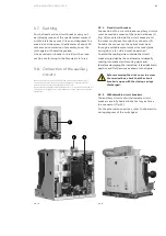
Page 43: ...f the standards Fig 14 9 8 1 Fixed circuit breaker Connection of the circuit breaker auxiliary circuits must be made by means of the terminal boxes 1 fig 14 mounted inside the circuit breaker and the wires must pass through the connector 2 Outside the connector the cables must pass through a suitable metal protective cover pipe wiring duct etc which must be earthed To avoid the cabling wires outsi...

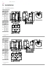
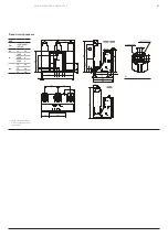
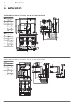
Page 44: ...VCD00002 E0148 Ur 12 kV Ir 630 A 1250 A Isc 16 kA 20 kA 25 kA 31 5 kA VM1 TN 1VCD00002 E0148 Ur 17 5 kV Ir 630 A 1250 A Isc 16 kA 20 kA 25 kA 31 5 kA 44 VM1 USER MANUAL 9 9 Overall dimensions Fixing interchangeable with the previous series 345 x 400 Fixing interchangeable with the previous series 345 x 520 Fixed circuit breakers Fixed circuit breakers Fixed circuit breakers 9 Installation ...

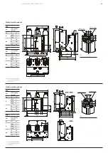
Page 45: ... 5 kA VM1 TN 1VCD00004 E0148 Ur 12 kV Ir 1600 A 2000 A 2500 A Isc 20 kA 25 kA 31 5 kA VM1 TN 1VCD00004 E0148 Ur 17 5 kV Ir 1600 A 2000 A 2500 A Isc 20 kA 25 kA 31 5 kA MEDIUM VOLTAGE PRODUCTS 45 45 Fixed circuit breakers Fixed circuit breakers Fixing interchangeable with the previous series 345 x 520 Fixing interchangeable with the previous series 345 x 650 ...

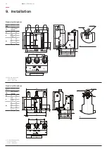
Page 46: ...5 kA VM1 TN 1VCD00006 E0148 Ur 24 kV Ir 630 A 1250 A Isc 16 kA 20 kA 25 kA 31 5 kA 46 VM1 USER MANUAL 9 Installation Fixing interchangeable with the previous series 345 x 520 Fixing interchangeable with the previous series 345 x 650 Fixed circuit breakers Fixed circuit breakers ...

Page 47: ...ø M M A VM1 TN 1VCD00007 E0148 Ur 24 kV Ir 1600 A 2000 A 2500 A Isc 16 kA 20 kA 25 kA MEDIUM VOLTAGE PRODUCTS 47 47 Fixing interchangeable with the previous series 345 x 650 Fixed circuit breakers ...

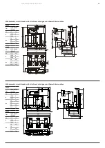
Page 48: ...A VM1 W 1 TN 1VCD00074 E0148 Ur 12 kV Ir 630 A 1250 A Isc 16 kA 20 kA 25 kA 31 5 kA VM1 W 1 TN 1VCD00074 E0148 Ur 17 5 kV Ir 630 A 1250 A Isc 16 kA 20 kA 25 kA 31 5 kA 48 VM1 USER MANUAL 9 Installation Withdrawable circuit breakers for UniGear switchgear and PowerCube modules Withdrawable circuit breakers for UniGear switchgear and PowerCube modules Only for PB2 PowerCube ...

Page 49: ... kA 31 5 kA VM1 P TN 1VCD00010 E0148 Ur 12 kV Ir 1600 A 2000 A Isc 16 kA 20 25 kA 31 5 kA VM1 P TN 1VCD00010 E0148 Ur 17 5 kV Ir 1600 A 2000 A Isc 16 kA 20 25 kA 31 5 kA MEDIUM VOLTAGE PRODUCTS 49 49 Withdrawable circuit breakers for UniGear switchgear and PowerCube modules Withdrawable circuit breakers for UniGear switchgear and PowerCube modules ...

Page 50: ...17 5 kV Ir 2000 A Isc 16 kA 20 kA 25 kA 31 5 kA VM1 P TN 1VCD00012 E0148 Ur 24 kV Ir 630 A 1250 A Isc 16 kA 20 kA 25 kA 50 VM1 USER MANUAL 9 Installation Withdrawable circuit breakers for UniGear switchgear and PowerCube modules Withdrawable circuit breakers for UniGear switchgear and PowerCube modules ...

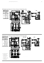
Page 51: ...E PRODUCTS 51 51 For PowerCube module up to 2000 A with natural ventilation For PowerCube module up to 2500 A with forced ventilation For UniGear up to 2300 A with natural ventilation For UniGear up to 2500 A with forced ventilation Withdrawable circuit breakers for UniGear switchgear and PowerCube modules Withdrawable circuit breakers for UniGear switchgear and PowerCube modules ...

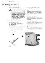
Page 52: ...after the 60 s time limit Dip Switch I 1004 1 must be enabled see par 7 1 7 Auto shutdown function for low voltage of the capacitor s 10 1 General procedures All the operations regarding putting into service must be carried out by ABB personnel or by suitably qualified customer personnel with in depth knowledge of the apparatus and of the installation Should the operations be prevented do not forc...

Page 53: ...sure the insulation resistance between the phases and the exposed conductive part of the circuit The insulation resistance should be at least 50 Mohm and in any case constant over time Auxiliary circuits With a 500 V megger if the apparatus installed allows this measure the insulation resistance between the auxiliary circuits and the exposed conductive part N B Before carrying out the test disconn...

Page 54: ... does not negatively affect the degree of vacuum of the interrupters Typical useful life expectancy of a VM1 vacuum circuit breaker is determined by the following factors embedded vacuum interrupter maintenance free up to 30 000 mechanical operating cycles drive with magnetic actuator maintenance free under normal service conditions up to 100 000 operating cycles for all the circuit breakers with ...

Page 55: ... specified in par 10 3 11 3 Servicing 11 3 1 Interruption devices in general If cleaning is found to be necessary during the inspections as specified in par 10 3 use the following procedure insulate the working area and make it safe by following the safety regulations specified in the IEC DIN VDE Standards general cleaning of the surfaces dry and eliminate any light deposits of dirt using a soft d...

Page 56: ...of the interrupter of the circuit breaker poles turn the power supply off and make the working area safe by following the safety regulations specified in the IEC DIN VDE Standards open the circuit breaker earth a terminal of each circuit breaker pole connect the earthed terminal of the VIDAR tester to the circuit breaker structure connect the high voltage terminal of the VIDAR tester to the termin...

Page 57: ...cuum interrupters is absolutely safe application of the withstand voltage at power frequency according to the IEC 62271 100 and VDE 0670 Standards is safe application of a voltage higher than the withstand voltage at power frequency or of a direct current test voltage specified in the IEC and VDE Standards cannot be used limitation of the above mentioned local phenomena with interrupters with open...

Page 58: ...nterventions in safe conditions Should the maintenance be carried out by the customer s personnel responsibility for the interventions remains with the customer Before carrying out any operation always make sure that the circuit breaker is open not supplied medium voltage circuit and auxiliary circuits and with the capacitors discharged To order circuit breaker spare parts accessories refer to the...

Page 59: ...MEDIUM VOLTAGE PRODUCTS 59 59 ...

Page 60: ...centers More service information abb com service 1VCD600182 V8773 Rev H en Instruction Manual 2022 03 VM1 gs The data and illustrations are not binding We reserve the right to modify the contents of this document following technical developments Copyright 2022 ABB All rights reserved ...

Reviews: