background image

16

16

VMAX

 -  INSTALLATION AND SERVICE INSTRUCTIONS

Auxiliary contacts of the circuit breaker
Un:  

24 ... 250 V AC-DC

Rated current:

Ith

2

 = 10 A

Insulation voltage:

2000 V 50 Hz (for 1 min)

Electrical resistance:

3 mOhm 

Rated current and breaking capacity in category AC11 and DC11:
Un 

Cos

ϕ


T

In 

Icu

220 V ~

0.7

--

2.5 A

25 A

24 V – 

--

15 ms

10 A

12 A

60 V – 

--

15 ms

6 A

8 A

110 V – 

--

15 ms

4 A

5 A

220 V – 

--

15 ms

1 A

2 A

Note
Application of the shunt opening release and/or additional shunt opening re-
lease foresees the use of one or two auxiliary make contacts (normally open), 
thereby reducing the number of auxiliary contacts available.

Motor operator (-MAS)
Un: 24 ... 30 - 48 ... 60 - 110 ... 130 - 220 ... 250 V–
Un: 100 ... 130 - 220 ... 250 V~ 50/60 Hz
Operating limits:   85 … 110% Un
Inrush power (Ps):  DC 600 W; AC = 600 VA
Rated power (Pn):   DC = 200 W; AC = 200 VA
Inrush time

0.2 s

Charging time: 

4-5 s

Insulation voltage: 2000 V 50 Hz (for 1 min)

Locking magnet on the operating mechanism (-RLE1)
Un: 24 - 30 - 48 - 60 - 110 - 132 - 220 - 250 V–
Un: 48 - 60 - 110 - 120 ... 127 - 220 ... 240 V~ 50/60 Hz
Operating limits: 

85 … 110% Un

Inrush power (Ps):

DC 250 W; AC = 250 VA

Continuous power (Pc):  DC = 5 W; AC  = 5 VA
Inrush time:

150 ms

Locking magnet on the truck (-RLE2)
Un: 24 - 30 - 48 - 60 - 110 - 125 - 127 - 132 - 220 - 240 V–
Un: 24 - 30 - 48 - 60 - 110 - 125 - 127 - 220 - 230 ... 240 V~ 50/60 Hz
Operating limits: 

85 … 110% Un

Inrush power (Ps):

DC 250 W; AC = 250 VA

Continuous power (Pc):  DC = 5 W; AC  = 5 VA
Inrush time:

150 ms

Device for monitoring the functionality and continuity of the 
shunt opening/closing releases (Shunt Test Unit)
Un:

24 ... 250 V AC/DC

Maximum interrupted current:

6 A

Maximum interrupted voltage:

250 V AC

5.5.  Characteristics of the electrical 
 accessories

Shunt opening release (-MBO1);
Additional shunt opening release (-MBO2);
Shunt closing release (-MBC)

Un: 24 - 30 - 48 - 60 - 110 - 125 - 220 - 250 V–
Un: 24 - 48 - 60 - 110 - 120 ... 127 - 220 ... 240 V~ 50 Hz
Un: 110 - 120 - 127 - 220 - 240 V~ 60 Hz
Operating limits:

70 … 110% Un

Inrush power (Ps): 

DC 200 W; AC = 200 VA

Inrush time

approx 100 ms

Maintenance power (Pc):

DC = 5 W; AC = 5 VA

Opening time:

40 ... 60 ms

Closing time:

40 ... 80 ms

Insulation voltage:

2000 V 50 Hz (for 1 min)

Undervoltage release (-MBU)

Un:  24 - 30 - 48 - 60 - 110 - 125 - 220 - 250 V–
Un:  24 - 48 - 60 - 110 - 120 - 127 - 220 ... 240 V~ 50 Hz
Un:  110 - 120 ... 127 - 220 ...  240 V~ 60 Hz
Operating limits:
– circuit breaker opening:

35-70% Un

–  circuit breaker closing: 

85-110% Un

Inrush power (Ps):

DC 200 W; AC = 200 VA

Inrush time 

approx 100 ms

Maintenance power (Pc)

DC = 5 W; AC = 5 VA

Opening time:

30 ms

Insulation voltage:

2000 V 50 Hz (for 1 min)

Electronic time delay device for undervoltage release (mounted 
outside the circuit breaker

Un: 24 ... 30 - 48 - 60 - 110 ... 127 - 220 ... 250 V–
Un: 48 - 60 - 110 ... 127 - 220 ...  240 V~ 50/60 Hz
Adjustable opening time
(r time delay device):

0.5-1-1.5-2-3 s

5.   Description

Summary of Contents for Vmax 12

Page 1: ...ions are carried out by qualified personnel with suitable knowledge of the apparatus Make sure that the standard and legal prescriptions are complied with during installation putting into service and maintenance so that installations according to the rules of good working practice and safety in the work place are constructed Strictly follow the information given in this instruction manual Responsi...

Page 2: ...ecial configurations Apart from this manual it is therefore always necessary to consult the latest technical documentation circuit and wiring diagrams assembly and installation drawings any protection coordination studies etc especially regarding any variants requested in relation to the standardised configurations Only use original spare parts for maintenance operations For further information pl...

Page 3: ...ce voltage the use of vacuum interrupters is absolutely safe application of the withstand voltage at industrial frequency according to the IEC 62271 100 and VDE 0670 Standards is safe application of a voltage higher than the withstand voltage at industrial frequency or of a direct current test voltage in direct current specified in the IEC and VDE Standards cannot be used limitation of the above m...

Page 4: ...he circuit breaker is shipped in special packing in the open position and with the springs discharged Each piece of apparatus is protected by a plastic cover to prevent any infiltration of water during the loading and unloading stages and to keep the dust off during storage ...

Page 5: ...in the shipping packing are instruction manual this document test certification identification label copy of the shipping documents electric wiring diagram Other documents which are sent prior to shipment of the apparatus are order confirmation original shipping advice note any drawings or documents referring to special configurations conditions 2 Checking on receipt Before carrying out any operat...

Page 6: ...sible the packing must be replaced using the original material supplied Insert hygroscopic packets inside the packing with at least one standard packet per piece of apparatus Should the original packing not be available and immediate installation is not possible store in a covered well ventilated dry dust free non corrosive ambient away from any flammable materials and at a temperature between 5 C...

Page 7: ... hooks 2 insert the hooks 2 in the special holes in the circuit breaker frame and lift on completion of the operation and in any case before putting into service unhook the lifting tool During handling take great care not to stress the insulating parts and the terminals of the circuit breaker Fig 2 Fig 3 The apparatus must not be handled by putting lifting devices directly under the apparatus itse...

Page 8: ...iliary circuits the proper terminal box is available The earthing hole is placed in the rear part of the circuit breaker Note there is a specific fixed version for UniGear switchgear with fixed CB called Vmax F 5 1 General The Vmax series of circuit breakers are pieces of apparatus under vacuum for indoor installation for the electrical performances please refer to the corresponding technical cata...

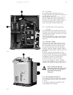
Page 9: ...vice for circuit breaker open closed 3 Rating plate 4 Opening pushbutton 5 Closing pushbutton 6 Undervoltage release mechanical override on request 7 Signalling device for closing springs charged discharged 8 Operation counter 9 Terminals 10 Earthing hole 11 Passage for the auxiliary circuit cord 12 Auxiliary contacts Fig 4 ...

Page 10: ...C Tropicalization IEC 60068 2 30 60721 2 1 Electromagnetic compatibility IEC 62271 1 This version cannot be sold loose this version can only be supplied for 2000 A Vmax FH version must be ordered together with ABB UniGear 500R switchgear Up to 15 kV 5 3 2 Standard fittings for fixed circuit breakers The basic versions of the fixed circuit breakers are three pole and fitted with EL type manual oper...

Page 11: ...6 16 20 20 20 20 25 25 25 25 25 25 25 25 25 25 25 2s 31 5 31 5 31 5 31 5 31 5 31 5 31 5 31 5 31 5 31 5 31 5 2s 40 40 40 40 50 50 50 50 63 63 63 63 63 63 63 63 63 63 65 80 80 80 80 80 80 80 80 80 80 82 33 60 33 60 33 60 33 60 27 32 5 10 15 10 15 10 15 10 15 10 17 5 43 75 43 75 43 75 43 75 50 30 60 30 60 30 60 30 60 45 80 496 534 543 543 543 543 534 21 02 416 416 416 416 416 416 416 16 38 421 456 46...

Page 12: ...acking in out operations by means of the special operating lever 16 The circuit breaker is completed with the isolating contacts 8 The withdrawable circuit breaker is fitted with special locks on the front crosspiece which allow hooking up into the corresponding couplings of the switchgear The locks can only be activated by the handles with the truck fully resting against the crosspiece The operat...

Page 13: ... 6 Signalling device for closing springs charged discharged 7 Operation counter 8 Isolating contacts 9 Slide for operating the switchgear shutters 10 Truck 11 Locks for hooking into the fixed part 12 Undervoltage release mechanical override on request 13 Strikers for activating the contacts placed in the enclosure 14 Connector plug 15 Cabling connection 16 Operating lever of circuit breaker rackin...

Page 14: ...es 600 mm wide and for UniSec switchgear The basic versions of the withdrawable circuit breakers are three pole and fitted with EL type manual operating mechanism mechanical signalling device for closing springs charged discharged mechanical signalling device for circuit breaker open closed closing and opening pushbutton operation counter set of ten auxiliary circuit breaker open closed contacts l...

Page 15: ...0 20 20 20 20 25 25 25 25 25 25 25 25 25 2s 25 25 25 25 31 5 31 5 31 5 31 5 31 5 31 5 31 5 31 5 31 5 2s 40 40 40 40 40 40 40 40 40 40 40 40 50 50 50 50 50 50 50 50 50 50 50 50 63 63 63 63 63 63 63 63 65 63 63 63 63 80 80 80 80 80 80 80 80 82 33 60 33 60 33 60 33 60 27 32 5 33 60 33 60 33 60 33 60 10 15 10 15 10 15 10 15 10 17 5 10 15 10 15 10 15 10 15 43 75 43 75 43 75 43 75 50 43 75 43 75 43 75 4...

Page 16: ...20 230 240 V 50 60 Hz Operating limits 85 110 Un Inrush power Ps DC 250 W AC 250 VA Continuous power Pc DC 5 W AC 5 VA Inrush time 150 ms Device for monitoring the functionality and continuity of the shunt opening closing releases Shunt Test Unit Un 24 250 V AC DC Maximum interrupted current 6 A Maximum interrupted voltage 250 V AC 5 5 Characteristics of the electrical accessories Shunt opening re...

Page 17: ... signalling parts Undervoltage release mechanical override on request Undervoltage release activated The circuit breaker can only be closed if the undervoltage release is supplied with power Undervoltage release disabled The circuit breaker can be closed even if the undervoltage release is not supplied Caption 1 Key lock if provided 2 Lever for manually charging the closing springs 3 Coupling leve...

Page 18: ... also be carried out remotely by means of a special control circuit Opening having taken place is indicated by the signalling device 6 6 3 Circuit breaker closing and opening operations Circuit breaker operation can be either manual or electrical fig 6 fig 7 a Manual spring charging operation To manually charge the closing springs it is necessary to repeatedly activate the charging lever 2 maximum...

Page 19: ...s in force in the relative countries 7 2 1 Normal conditions Follow the recommendations in the IEC 60694 and 62271 100 Standards In more detail Ambient temperature Maximum 40 C Average maximum over 24 hours 35 C Minimum according to class 5 apparatus for indoor installation 5 Humidity The average value of the relative humidity measured for a period longer than 24 hours must not exceed 95 The avera...

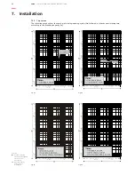
Page 20: ... show the number of closing opening cycles No allowed of the vacuum interrupters according to the breaking capacity Ia Caption Nr Number of closing opening cycles allowed for the vacuum interrupters Ia Breaking capacity of the vacuum interrupters Fig 8a Fig 8b Fig 8c Fig 8d 7 Installation ...

Page 21: ...it breakers with ABB truck for UniGear ZS1 550 mm wide and UniSec switchgear The withdrawable circuit breakers are preset for use in UniGear type ZS1 switchgear 550 mm wide For racking in racking out of the switchgear fully insert the lever 1 fig 9 in the appropriate seat 2 and work it clockwise for racking in and anti clockwise for racking out until the limit switch positions are reached Circuit ...

Page 22: ...ts received According to the conductor material and the surface treatment used carry out the operations indicated in table T1 on the contact surface of the conductor Assembly procedure Put the connections in contact with the circuit breaker terminals taking care to avoid mechanical stresses traction compression on for example the conducting busbars on the terminals Interpose a spring washer and a ...

Page 23: ...ade by means of the proper terminal box mounted inside the circuit breaker and the wires must pass through the connector 2 Outside the connector the cables must pass through a suitable metal protective covering pipe wiring duct etc and be earthed To prevent the cabling wires outside the circuit breaker provided by the customer from accidentally coming into contact with moving parts and therefore d...

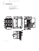
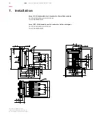
Page 24: ... 24 VMAX INSTALLATION AND SERVICE INSTRUCTIONS 7 10 Overall dimensions Vmax Fixed circuit breakers 12 17 5 kV 630 1250 A 16 20 25 31 5 kA TN 1VCD003279 V3198 Insulating shields for 17 5 kV 7 Installation ...

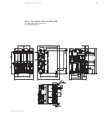
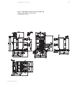
Page 25: ...DISTRIBUTION SOLUTIONS 25 25 Vmax F Fixed circuit breakers for UniGear 500R 12 17 5 kV 630 1250 A 25 31 5 kA TN 1VCD003516 E0771 Insulating shields for 17 5 kV ...

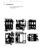
Page 26: ... A 17 51 5 543 28 108 49 26 5 79 5 105 20 59 58 5 173 29 5 48 320 155 5 189 426 5 243 112 7 9 5 135 5 562 86 5 11 5 47 218 240 VMAX INSTALLATION AND SERVICE INSTRUCTIONS Vmax F Fixed circuit breakers for UniGear 500R 12 17 5 kV 1600 2000 A 25 31 5 kA TN 1VCD003558 V2315 Insulating shields for 17 5 kV 7 Installation ...

Page 27: ...DISTRIBUTION SOLUTIONS 27 27 Vmax L Withdrawable circuit breakers for UniGear 550 12 17 5 kV 630 1250 A 16 20 25 31 5 kA TN 1VCD003334 V2296 Insulating shields for 17 5 kV ...

Page 28: ... 56 5 2 22 31 1 22 28 1 09 28 1 09 49 1 93 28 1 09 501 19 72 68 2 68 124 4 88 456 17 95 150 5 91 150 5 91 1 2 VMAX INSTALLATION AND SERVICE INSTRUCTIONS Vmax W Withdrawable circuit breakers for PowerCube modules 12 17 5 kV 630 1250 A 16 20 25 31 5 kA TN 1VCD003280 V3519 1 Insulating shields for 17 5 kV 2 Electrical field distributor for 17 5 kV Note dimensions in brackets are in inches Vmax SEC Wi...

Page 29: ... resistance should be at least 50 Mohm and in any case constant over time The insulation resistance should be a few Mohm and in any case constant over time 2 Auxiliary circuits Check that the connections to the control circuit are correct proceed at the relative power supply Operations and signals are normal 3 Manual operating mechanism Carry out a few closing and opening operations see cap 6 N B ...

Page 30: ...wer attempt circuit breaker closing Closing is not possible 11 Locking electromagnet RLE1 if provided With the circuit breaker open springs charged and locking electromagnet not supplied attempt circuit breaker closing both manually and electrically Closing is not possible 12 Locking electromagnet on the truck circuit breaker RLE2 if provided With the circuit breaker open in the isolated for test ...

Page 31: ...lled in at least to check the service performances and for repair work During maintenance work turn the power supply off and put the apparatus under safe conditions 9 1 1 Operating life Operating life expectancy of Vmax vacuum circuit breakers is as follows vacuum interrupter up to 30 000 operations according to the type see par 7 2 3 Trip curves actuator up to 10 000 operations under normal opera...

Page 32: ... insulate the working area and make it safe respecting the safety regulations specified in the IEC DIN VDE Standards Checking screw tightening general cleaning of surfaces dry and eliminate any light deposits of dirt using a soft dry cloth more resistant deposits of dirt can be removed using a slightly alkaline domestic cleanser cleaning insulating surfaces and conductive parts light dirt with Riv...

Page 33: ... circuit breaker structure connect the high voltage terminal of the VIDAR tester to the terminal not connected to earth of the interrupter L1 phase and carry out the test Repeat the test for phases L2 and L3 Note The tester connection cables can produce an indication due to the capacitive effect In this case the cables must not be removed 9 3 4 Lubrication Visually inspect the lubrication conditio...

Page 34: ...g closing springs charged discharged Circuit breaker auxiliary contacts Locking electromagnet on the operating mechanism Position contact of the withdrawable truck Contacts signalling racked in isolated Key lock in open position Isolation interlock with the door Protection for opening pushbutton Protection for closing pushbutton Locking electromagnet on the withdrawable truck Set of six tulip cont...

Page 35: ...DISTRIBUTION SOLUTIONS 35 35 ...

Page 36: ...vice information abb com service 1VCD 600189 Rev N en Instruction Manual 2018 05 Vmax gs For more information please contact The data and illustrations are not binding We reserve the right to modify the contents of this document following technical developments Copyright 2018 ABB All rights reserved ...

Reviews: