background image

4

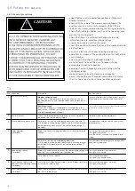
THE CIRCuIT-bREAkERS DESCRIbED IN 
THIS bOOk ARE DESIGNED AND TESTED 
TO OPERATE wITHIN THEIR NAMEPLATE 
RATING. OPERATION OuTSIDE OF THESE 
RATINGS MAy CAuSE EquIPMENT TO 
FAIL, RESuLTING IN PROPERTy DAMAGE, 
bODILy INjuRy AND/OR DEATH.
ALL SAFETy CODES, SAFETy STANDARDS 
AND/OR REGuLATIONS AS THEy MAy bE 
APPLIED TO THIS TyPE OF EquIPMENT 
MuST bE ADHERED TO STRICTLy. 
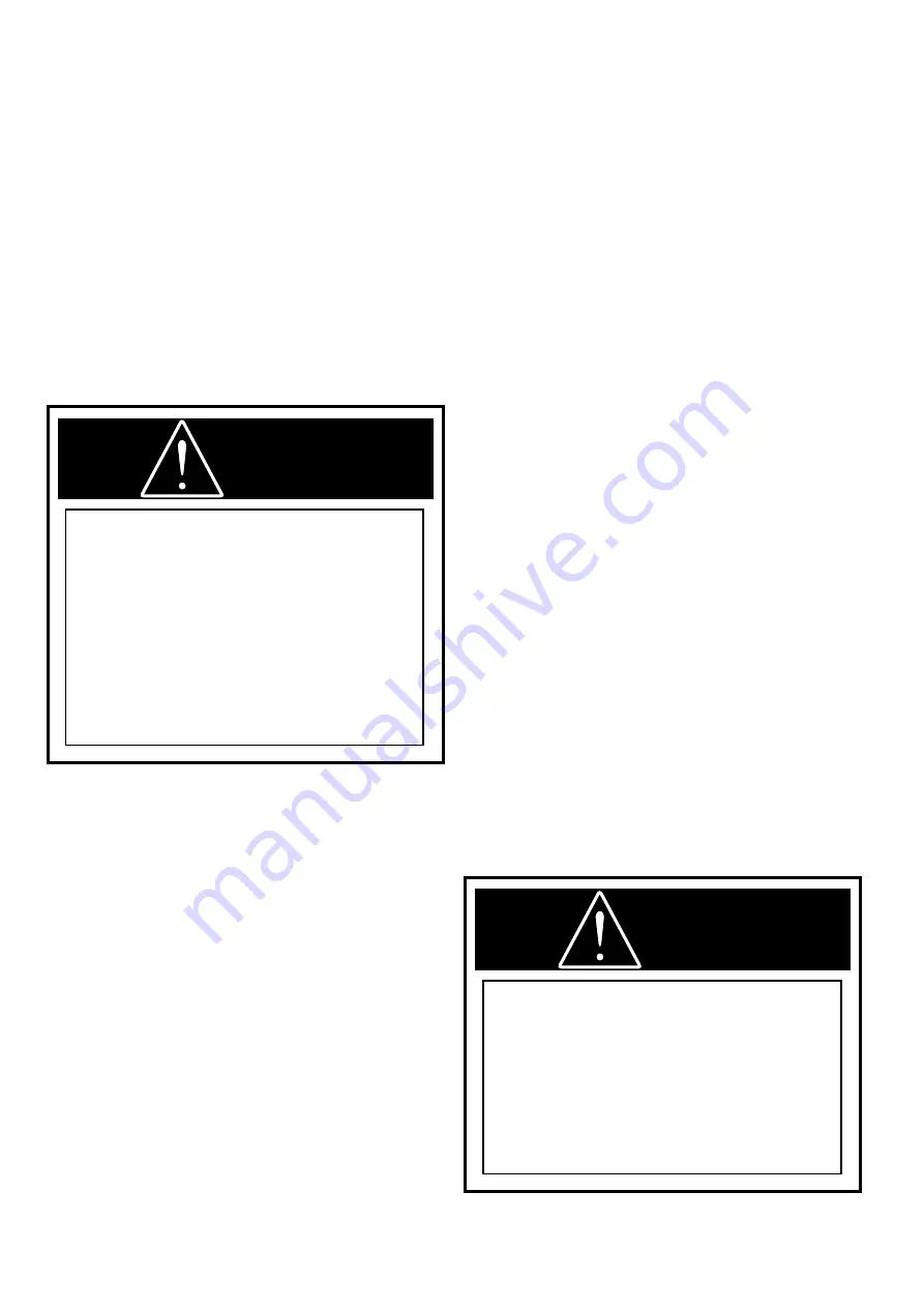
WARNING

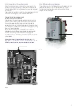
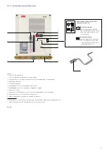
2.Introduction and safe practices

2.1. Introduction 

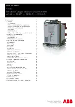
The purpose of this manual is to provide instructions for 
unpacking, storage, installation, operation, and maintenance 
for Vmax/w and Vmax vacuum circuit-breakers. This 
manual should be carefully read and used as a guide during 
installation, initial operation, and maintenance. 

The specific ratings of each model circuit-breaker are listed 
on the individual nameplates. The Vmax/w and Vmax circuit-
breakers are protective devices. As such, they are maximum 
rated devices. In no event should they be applied outside of 
their nameplate ratings.
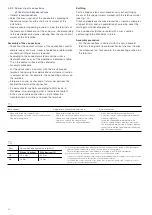
2.2. Safe practices 

Vmax/w and Vmax circuit-breakers are equipped with high 
energy / high speed mechanisms. The design includes several 
interlocks and safety features which help ensure safe and 
proper operating sequences. To ensure safety of personnel 
associated with installation, operation, and maintenance of 
these circuit-breakers, the following recommendations must 
be followed.

Only qualified persons, as defined in the National Electric 
Safety Code, who are familiar with the installation and 
maintenance of medium voltage circuits and equipment 
should be permitted to work on these circuit-breakers

Read these instructions carefully before attempting any 
installation, operation, or maintenance of these power circuit-
breakers. 

do not work on an energized circuit-breaker. 

do not work on a circuit-breaker unless all components 
are disconnected by means of a visible break and 
securely grounded. 

do not work on a circuit-breaker with power supplied to 
the secondary control circuit. 

do not defeat safety interlocks. this may result in bodily 
injury, death and/or equipment damage. 

do not work on a closed circuit-breaker. 

do not work on a circuit-breaker with charged energy 
(springs charged). 

do not use a circuit-breaker by itself as the sole means of 
isolating a high voltage circuit. 

do not leave a circuit-breaker in an intermediate 
position in a cell. always place the circuit-breaker in the 
disconnect or connect position. 

FAILuRE TO ObSERVE THE 
REquIREMENTS OF OSHA STANDARD 
1910.269 CAN CAuSE DEATH OR SEVERE 
buRNS AND DISFIGuREMENT. THAT 
STANDARD SPECIFICALLy PROHIbITS 
THE wEARING OF POLyESTER, ACETATE, 
NyLON, OR RAyON CLOTHING by 
EMPLOyEES wORkING wITH EXPOSuRE 
TO ELECTRIC ARCS OR FLAMES.

NOTICE

Summary of Contents for Vmax

Page 1: ... 3 1 Receiving 6 3 2 Handling 7 3 3 Storage 8 4 Description 9 4 1 General 9 4 2 Reference Standards 9 4 3 Fixed circuit breaker 9 4 4 Characteristics of the electrical accessories 13 4 5 Preliminary operations 14 4 6 Putting into service 18 4 7 Standard fittings for circuit breaker 27 5 Operation installation and maintenance 28 5 1 Interlocks 28 5 2 Maintenance 30 5 3 Truck 35 6 Servicing 38 6 1 I...

Page 2: ......

Page 3: ...e so that installations according to the rules of good working practice and safety in the work place are constructed Strictly follow the information given in this instruction manual Check that the rated performance of the apparatus is not exceeded during service Check that the personnel operating the apparatus have this instruction manual to hand as well as the necessary information for correct in...

Page 4: ...aker styles All information in this booklet was current at the time of printing Unless otherwise noted all references in this booklet are determined by viewing the circuit breaker from the front Only use original spare parts for maintenance operations For further information please also see the technical catalogue of the circuit breaker 1 2 Environmental protection programme The Vmax W and Vmax ci...

Page 5: ...mission Standards One of the physical properties of vacuum insulation is the possibility of X ray emission when the interrupter contacts are open The specific tests carried out at the PTB laboratories Physikalisch Technische Bundesanstalt in Brunswick Germany show that local emission at a distance of 10 cm from the interrupter or pole surface does not exceed 1 mSv h It follows that at the rated se...

Page 6: ...allation operation and maintenance of these circuit breakers the following recommendations must be followed Only qualified persons as defined in the National Electric Safety Code who are familiar with the installation and maintenance of medium voltage circuits and equipment should be permitted to work on these circuit breakers Read these instructions carefully before attempting any installation op...

Page 7: ...ity measured for a period longer than 24 hours must not exceed 95 The average value of the pressure of the water vapour without condensation measured for a period longer than 24 hours must not exceed 2 2 kPa The average value of the relative humidity measured for a period longer than 1 month must not exceed 90 The average value of the pressure of the water vapour measured for a period longer than ...

Page 8: ...ber carton number and part numbers of damaged or missing parts should accompany the claim On receipt check the state of the apparatus integrity of the packing and correspondence with the nameplate data see fig 1 with what is specified in the order confirmation and in the accompanying shipping notes Also make sure that all the materials described in the shipping notes are included in the supply Sho...

Page 9: ...o lift and handle the circuit breaker proceed as follows fig 2 use a special lifting tool 1 not supplied fitted with ropes with safety hooks 2 insert the hooks 2 in the special holes in the circuit breaker frame and lift on completion of the operation and in any case before putting into service unhook the lifting tool During handling take great care not to stress the insulating parts and the termi...

Page 10: ...rosive ambient away from any flammable materials and at a temperature between 30 C and 45 C Circuit breakers should be installed in their permanent location as soon as possible If the circuit breakers are not placed in service for some time it is advisable to provide adequate means of environmental protection This may be done by keeping the circuit breaker in its original shipping container and st...

Page 11: ...e electrical performances please refer to the corresponding technical catalogue code 1VCP000408 For special installation requirements please contact ABB The following versions are available fixed withdrawable for ABB PowerCube modules 4 2 Reference Standards The Vmax circuit breakers conform to the IEC 62271 100 ANSI C37 04 C37 54 C37 09 C37 55 Standards and those of major industrialized countries...

Page 12: ...board Circuit breaker Vmax 15 Fixed version Standards IEC 62271 100 CEI EN62271 100 file 7642 C37 54 C37 09 C37 04 C37 55 UL Recognized Component Mark Rated voltage Ur kV 15 Rated insulation voltage Us kV 15 Withstand voltage at 50 Hz Ud 1 min kV 36 at 60 Hz Impulse withstand voltage Up kV 95 Rated frequency fr Hz 60 Rated normal current 40 C Ir A 1200 Rated breaking capacity rated symmetrical sho...

Page 13: ...ides 9 for operating the segregation shutters of the medium voltage contacts of the enclosure or of the switchgear are fixed on the sides of the circuit breaker On the front part of the circuit breaker truck the crosspiece is mounted with the handles 17 for hooking up the circuit breaker for the racking in out operations by means of the special operating lever 16 The circuit breaker is completed w...

Page 14: ...ing time ms 27 32 5 Arc duration ms 10 17 5 Total interruption time ms 50 Closing time ms 45 80 Maximum overall dimensions H mm in 665 26 18 W mm in 503 19 80 D mm in 662 26 06 Pole centre I mm in 150 5 91 Weight kg lb 98 215 60 Standardized table of dimensions 1VCD003280 Operating temperature C 30 40 Tropicalization IEC 60068 2 30 60721 2 1 Electromagnetic compatibility IEC 62271 1 Standard fitti...

Page 15: ... to VDE 0110 standard Group C 660 V AC 800 V DC Rated voltage 24 V 660 V Test voltage 2 2 kV Rated overcurrent 10 A Number of contacts 5 Contact run 6 mm 7 mm Activation force 26 N Resistance 3 mΩ Storage temperature 20 C 120 C Operating temperature 20 C 70 C Contact overtemperature 20 K Number of cycles 30 000 Unlimited breaking capacity if used with 10 A fuse in series Note Application of the sh...

Page 16: ...nnel 2 Pull Handles to center this withdraws Cell Interlock Tabs allowing breaker to be removed 4 Pull the breaker from Circuit Breaker Compartment with the Handles onto the required transportation device 4 5 3 Withdrawable circuit breakers with truck made by third parties The Vmax circuit breakers installed on trucks made by the customer must be fitted with one or two additional auxiliary contact...

Page 17: ... the connector 1 Fig 8 Outside the connector the cables must pass through a suitable metal protective covering pipe wiring duct etc and be earthed To prevent the cabling wires outside the circuit breaker provided by the customer from accidentally coming into contact with moving partsand therefore damaging the insulation the wires should be positioned and fixed as shown in the figure 8 Before remov...

Page 18: ... again with Vaseline grease Use a conductor busbar or cord with a cross section conforming to the Standards in force Assembly procedure Put the connections in contact with the circuit breaker terminals taking care to avoid mechanical stresses traction compression on for example the conducting busbars on the terminals Bare copper Clean with a fine file or emery cloth Tighten fully and cover the con...

Page 19: ...er for manually charging the closing springs 3 Coupling lever for racking out operation only for withdrawable circuit breakers 4 Opening pushbutton 5 Closing pushbutton 6 Signalling device for circuit breaker open closed 7 Signalling device for closing springs charged discharged 8 Operation counter 9 Handles for operating the truck locks only for withdrawable circuit breakers 10 Operating lever fo...

Page 20: ... exposed conductive part of the circuit The insulation resistance should be at least 50 Mohm and in any case constant over time Auxiliary circuits With a 500 V megger if the apparatus installed allows this measure the insulation resistance between the auxiliary circuits and the exposed conductive part The insulation resistance should be a few Mohm and in any case constant over time 2 Auxiliary cir...

Page 21: ...not possible Carry out a few closing and opening operations N B Supply the undervoltage release and the locking magnet on the operating mechanism at the relative rated voltage if provided The geared motor recharges the springs after each closing operation 12 Locking electromagnet on the truck circuit breaker RL2 if provided With the circuit breaker open in the isolated for test position and the lo...

Page 22: ...rtation device 4 The circuit breaker is now in the withdrawn position 4 6 4 Racking Vmax W Figure 7 Vmax W circuit breakers are designed with two positive racking positions Disconnect Connect In the Disconnect position the shutters are closed Manual opening is allowed Electrical operation of the circuit breaker is allowed with control power supplied through the secondary contacts with the shutters...

Page 23: ...r shows OPEN c cut off the power supply to the auxiliary circuit d open the enclosure door following Powercube Installation and maintenance instructions 647652 001 sec 6 3 e remove the circuit breaker metallic front protection shield f using the manual lever carry out an emergency racking out operation keeping the moving anchor A Fig 12 of the locking magnet RL2 pressed left by means of a screwdri...

Page 24: ...22 C Secondary disconnects B Shutters Wheel rails Compartment slots A Fig 13 Fig 14 Racking screw collar ...

Page 25: ...g charging shunt closing release shunt opening release The geared motor automatically recharges the springs after each closing operation until the yellow signaling device 7 appears If the power is cut off during charging the geared motor stops Automatically the motor spring charging starts recharging the springs when the power returns In any case it is always possible to complete the recharging op...

Page 26: ...es the closing springs Once the closing spring is charged completely 4 A part of the closing springs force works on the closing hook through the closing lever assembly and the pin 1 fig 17 of the cams toggle assembly 5 The closing hook remains locked by the closing shaft 2 fig 17 6 The opening hook 3 fig 17 reaches its position and receives the central hook of the cams toggle assembly 7 The signal...

Page 27: ...clockwise 5 fig 18 12 The signalling indicator device for open closed CB status goes in close position the CB is closed 13 The long levers reach the settled position 14 The contact springs inside the poles and the opening spring inside the frame are charged 15 A part of the contact springs and opening spring load works on the long levers but the long levers remain in their position by the central ...

Page 28: ...e opening shaft 1 fig 21 turns and releases the opening hook 19 The opening hook releases the central hook of the cams toggle assembly 20 The long levers of the cams toggle assembly are free now and by the force of the contact springs and the opening spring they can move 21 The main shaft turns clockwise 22 The signalling device for open closed CB goes in open position 23 The CB is in open positio...

Page 29: ...nserted into the socket if the rated current of the circuit breaker is different from the rated current of the panel 11 racking in out lever 16 fig 7 the quantity must be defined according to the number of pieces of apparatus ordered 12 locking electromagnet in the truck 7 fig 27 RL2 This prevents the circuit breaker being racked into the panel with the auxiliary circuits disconnected plug not ins...

Page 30: ... if the withdrawable truck is exactly in the defined disconnected position or in the connected position electric interlock the circuit breaker can be opened manually in the service or test position when it is not powered the switchgear is provided with devices which only allow connection and disconnection of the plug connector 3 fig 2A in the test isolation position 5 1 2 Interlocks in the case wh...

Page 31: ...e base plate 2 fig 25 This prevents movement of the withdrawable truck and therefore movement of the circuit breaker 2 to prevent closing of an intermediate circuit breaker position The slide locking device 3 fig 25a on the circuit breaker can be used for this purpose if the Vmax circuit breaker fitted on non ABB truck is in intermediate position the slide locking device must be pulleed down as sh...

Page 32: ...fe The drive is maintenance free for its whole operating life and only requires functional inspections The vacuum interrupters are maintenance free for their whole operating life Vacuum interruption does not produce harmful effects even when there are frequent trips at the rated and short circuit current The servicing interventions and their aim depend on the environmental conditions on the sequen...

Page 33: ...by environmental agents by the frequency of operation and by the number of trip operations under short circuit 5 2 2 Mechanism The mechanism requires visual inspection of hardware lubrication and operation during routine inspection Remove the front cover by unfastening its screws and correct any loose or missing hardware Always lubricate the working surface of the moving parts Verify lubrication o...

Page 34: ...servicing measures must be taken see the paragraph on Servicing Functional test Make the circuit breaker safe by discharging the closing springs close and open the circuitbreaker by means of the closing and opening pushbuttons With the circuit breaker in the test position carry out a few opening and closing operations by means of the shunt opening and closing releases The nuts and screws are tight...

Page 35: ...ission system A functional test of the drive must be carried out when the number the number of operating cycles indicated has been exceeded after 10 000 operation or during maintenance operations Before carrying out the functional test open the circuit breaker and take it to the test position withdrawable circuit breaker or insulate the working area and make it safe in conformity with the safety r...

Page 36: ...ing life of the vacuum interrupter is defined by the sum of the ultimate currents corresponding to the specific type of interrupter when the sum of the ultimate currents is reached the complete VI must be replaced for electrical life ask to ABB Note Dismantling and replacement of the interrupter assembly can only be carried out by ABB personnel or by qualified and specially trained personnel espec...

Page 37: ... by hand movement Replace or tighten any missing or loose hardware With the circuit breaker outside the cell rotate the racking screw as though racking the circuit breaker to the Connect position This process will expose surfaces inside the truck that need to be inspected and lubricated Lubricate the exposed parts specifically the entire Racking Screw 4 Inspect the circuit breaker locking tabs 3 f...

Page 38: ...oltage testing and lubrication of the primary contacts should occur as outlined hereinafter All insulation material should be clean and free of cracks and replace damaged parts Dirt or dust may create a dielectric path to ground on the insulation Remove dust and dirt with a clean lint free cloth Apply distilled water to the cloth to remove any difficult dirt DO NOT return the circuit breaker into ...

Page 39: ...y DC testing is not considered a valid test for vacuum integrity Testing with meggers or other similar devices is not considered valid under any circumstances 5 3 3 Application of the X ray Emission standards One of the physical properties of vacuum insulation is the possibility of X ray emission when the interrupter contacts are open The specific tests carried out at the PTB laboratories Physikal...

Page 40: ...tably qualified and specially trained personnel 6 4 Vacuum interrupters The vacuum interrupters are maintenance free up to the maximum number of electrical operations The operating life of the vacuum interrupter is defined by the sum of the ultimate currents corresponding to the specific type of interrupter when the sum of the ultimate currents is reached the complete VI must be replaced for elect...

Page 41: ...auxiliary contacts Locking electromagnet on the operating mechanism Position contact of the withdrawable truck Contacts signalling racked in isolated Key lock in open position Isolation interlock with the door Protection for opening pushbutton Protection for closing pushbutton Locking electromagnet on the withdrawable truck Set of six tulip contacts 7 Spare parts and accessories All assembly opera...

Page 42: ... 5 0 33 421 16 57 364 14 33 496 19 53 40 1 56 35 1 38 28 1 1 336 13 23 291 11 46 534 21 02 104 5 4 11 10 0 39 176 6 93 49 1 93 416 16 37 29 1 12 29 1 12 16 0 61 57 2 22 30 1 16 48 1 89 320 12 6 48 1 89 188 7 39 32 1 26 3 1 8 10 2 10 8 Overall dimensions Vmax Fixed circuit breaker ANSI 15 kV 1200 A 25 31 5 kA 1VCD003279_V3198 Dimensions are in mm and in inches ...

Page 43: ...5 5 0 61 370 14 58 19 5 0 77 662 26 05 36 1 42 79 3 11 39 1 53 52 2 05 320 12 6 25 0 98 416 16 38 598 23 54 21 5 0 85 154 6 06 76 2 99 629 5 24 78 625 5 24 63 123 5 4 86 260 10 24 205 8 07 35 1 38 501 19 72 68 2 68 124 4 88 456 17 95 150 5 91 150 5 91 Vmax W Withdrawable circuit breakers for PowerCube ANSI 15 kV 1200 A 25 31 5 kA 1VCD003280_V2856 Dimensions are in mm and in inches ...

Page 44: ...stor general symbol Passing make contact closing momentarily when its operating device is released Position switch limit switch make contact Position switch limit switch brake contact Circuit breaker with automatic release Operating device general symbol Lamp general symbol Graphical symbols for electrical diagrams 617 IEC Standards Circuit diagram of Vmax circuit breaker in withdrawable version f...

Page 45: ...43 ...

Page 46: ...44 ...

Page 47: ...45 ...

Page 48: ...e note H SC Pushbutton or contact for the circuit breaker closing SO Pushbutton or contact for the circuit breaker opening XB Connector for the circuit breaker circuits XB2 9 Connectors of accessories XB1 Switchboard terminal board mounted externally to the circuit breaker RL1 Locking magnet If de energized it prevents the circuit breaker closing mechanically it is possible to limit it consumption...

Page 49: ...undervoltage release deactivate Incompatibility The combinations of circuits given in the figures below are not possible on the same circuit breaker 3 4 31 31 33 34 4 31 32 3 33 34 31 32 52 33 34 51 51 52 Notes A The circuit breaker is delivered complete with the accessories listed in the ABB order acknowledgement only To draw up the order examine the catalogue B The undervoltage release is availa...

Page 50: ...l at the end of product life During disposal of the product it is always necessary to act in accordance with local legal requirements in force Methods of disposal Disposal can either be carried out thermally in an incineration plant or by storing on a waste site RAW MATERIAL RECOMMENDED METHOD OF DISPOSAL Metal material Fe Cu Al Ag Zn W others Separation and recycling Thermoplasts Recycling or dis...

Page 51: ......

Page 52: ...n www abb com productguide 1VCD600929 Rev B en Instruction booklet 2011 01 gs The data and illustrations are not binding We reserve the right to make changes without notice in the course of technical development of the product Copyright 2011 ABB All rights reserved ...

Reviews: