background image

  VMS user manual 

10

Maintenance 

Maintenance intervals: 

The maintenance intervals depend on the intensity of use of the switchgear 
installed in the switchboard and can be either preventive or repair work, but should 
always be in accordance with local regulations and standards (i.e. NEN3140). 

Attention:


Observe all relevant operating instructions of the electrical components as well as 
local requirements, regulations and standards (i.e. NEN3140). 

Inspection interval:


A visual inspection as well as a control of mechanical functions (e.g. interlocks etc.) 
of the assembly should be done every 4 years as a minimum. 
An interval of <= 1 year is recommended. 

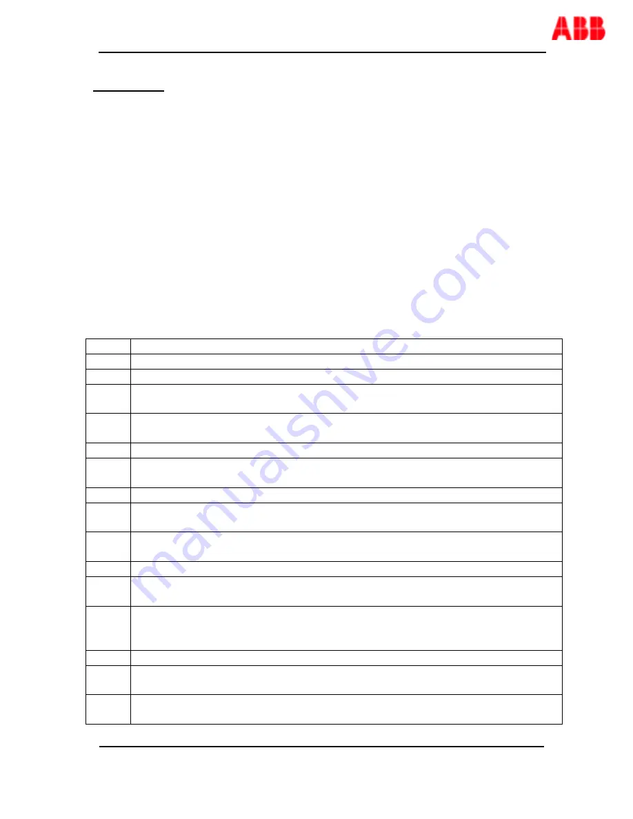
The following checklist can be applied as a guideline during inspection. 

Inspection / corrective action 

inspection of service conditions


(visual) inspection of the assembly


inspection of the ventilation openings clean ventilation openings / change dust 
filters


inspection of measures to achieve IP rating,


no ingress of condensation. Unused 

gland opening 

inspection of cables & 

glanding’s


inspection on the effects of pollution, clean with dry piece of cloth or use 
vacuum cleaner / do not use high pressure air! 

inspection for damages


inspection on the effects of corrosion, repair failures on surface / make dry if 
necessary 

inspection of sub-assemblies & electrical components maintenance in 
accordance with relevant component manuals 

10 

inspection of connectors & terminals 

11 

check correct protection of electrical components & cables, change fuses if 
necessary (decoloring, correctly placed) 

12 

check settings of electrical components (e.g. overload & short circuit protection) 
correct settings according the documentation of the electrical component. Test 
Residual Current (earth leakage) devices. 

13 

inspection of plug-in contacts remove old grease, put new grease on 

14 

inspection of measures against electrical shock (PE conductor, PE connections) 
check insulation resistance (earth resistance /dielectric testing).  

15 

check  torque  values  for  electrical  connections  (see  torque  values  for  electrical 
connections), 

µΩ testing of busbar 

system 

Summary of Contents for VMS

Page 1: ...Modular Insulated Distribution System VMS User manual ...

Page 2: ...VMS user manual 2 Table of contents 1 Introduction 3 2 Dimensions and Technical Spec 3 3 Shipping Packing Lifting 4 4 Installation 5 5 Working with the system 9 6 Maintenance 10 7 Contact details 12 ...

Page 3: ...em can be provided as loose components or factory assembled Designed for wall mounting or floor standing installation Modular coupling possibilities in width and height Standards EN IEC 61439 2 EN IEC 60529 EN IEC 62262 Dimensions and Technical Specifications Type Designation VMS Type of material Glass fiber reinforced Polycarbonate Method of fixing Wall floor Intended location Indoor Limited Outd...

Page 4: ...n as it is unpacked If found damaged immediately contact the manufacturer at the numbers mentioned in contact details section 3 The company cannot be held responsible for any damage caused due to improper storing CAUTION Improper storing can cause damage to the enclosure Do not stack one enclosure over another while storing or during transportation 4 Use a pallet truck for transportation of the en...

Page 5: ... covers that can be opened by authorized operating personnel only Procedure for installing the enclosure on a wall Remove any obstruction dirt etc from the location Make sure the floor and wall surface is levelled The enclosure can be mounted on a wall by using brackets up to 5 enclosures or a supporting frame The brackets can be positioned 0 45 90 screw through the base corner holes Installation ...

Page 6: ...iles equal to the number of vertical sections 1 If the unit height is greater than 1000 mm three horizontal C profiles will be used The vertical C profiles are 140 mm longer than the height of the assembled panel The frame and the enclosure assembly should be mounted simultaneously Horizontal and vertical C profiles of the first row of enclosures are assembled together by clamping brackets and sli...

Page 7: ...VMS user manual 7 Following rows are then assembled the same way Frame and enclosure assemblies are mounted simultaneously ...

Page 8: ...l Z profiles at each partition extension The Z profiles are bolted together by means of 2 C profiles and sliding nuts M8 bolts for fixation The VMS boxes can be mounted directly on the front of the Z profiles by means of M5 x 16 Torx screws The Z profiles can be mounted on the floor using the stand supports ...

Page 9: ...ver should be opened Opening the covers 1 Unlock the cover s Use an appropriate screwdriver that matches the cover screws 2 Remove the cover s 3 Feeder switches can be operated Fuses can be replaced In cases where access to the busbar system is required additionally the cover plates can be removed by using a slotted screw driver The protective space is now accessible and all necessary service and ...

Page 10: ...eve IP rating no ingress of condensation Unused gland opening 5 inspection of cables glanding s 6 inspection on the effects of pollution clean with dry piece of cloth or use vacuum cleaner do not use high pressure air 7 inspection for damages 8 inspection on the effects of corrosion repair failures on surface make dry if necessary 9 inspection of sub assemblies electrical components maintenance in...

Page 11: ...call attention to information that is especially significant to understanding and operating the equipment This document is based on information available at the time of its publication While efforts have been made to ensure accuracy the information contained herein does not cover all details or variations in hardware and software nor does it provide for every possible contingency in connection wit...

Page 12: ...VMS user manual 12 Contact Please make sure that you have the Nominal Plate data before calling the service numbers ...

Reviews: