Quick installation guide
VSN300 WIFI LOGGER CARD
ABB Solar inverters
1.
Product Identification - Labels and Symbols
3.
Main components
5.
List of supplied components
6.
Assembly Instructions
Operating diagram
2.
Enviroment and obstacles evaluation
4.
EN
In addition to the notes below, please read and follow the safety and installation information
provided in the installation manual. The technical documentation for the product is available
on the website www.abb.com/solarinverters
This equipment must be used following the guidelines provided in the manual.
Preliminary operation
The inside of the inverter may be accessed only after the inverter has been disconnected from the grid and from the photovoltaic generator.
The VSN300 WIFI LOGGER CARD must be installed only by trained professional installers
-
Turn off the inverter by physically disconnecting the AC and DC voltages, as well as any voltage connected to the multifunction relay.
10
Wait for the amount of minutes according to the indication on the inverter’s label in order to allow discharging any stored energy in the
inverter and use safety clothing and/or personal protective equipment
-
Open the inverter front cover.
Antenna installation
The antenna must be installed outside the inverter in place of a service cable gland (size
M20)
-
Remove one of the M20 service cable glands of the inverter (using a 25mm wrench).
-
Pass the antenna connection cable into the inverter by passing it through the M20 cable
gland opening, the gasket, the plastic lock nut and the adapter (If used).
-
Attach the antenna bulk head connector to the inverter using the supplied plastic
lock nut (torque 5N-m). For some inverter models (UNO-2.0/2.5-I-OUTD and TRIO-
5.8/7.5/8.5-TL-OUTD) it will be necessary to use the adapter kit due to the greater
thickness of the inverter enclosure. In this case, proceed as follows:
-
Install the gasket on the adapter
-
Attach the adapter to the inverter using the plastic lock nut (torque 5N-m).
-
Pass the antenna connection cable into the inverter by passing it through the M20
cable gland opening, the adapter, the gasket and the nut.
-
Attach the antenna bulk head connector to the adapter (torque 5N-m).
-
Screw the antenna on the support
Use only antenna type RF Technology Corp. Model EA-79 F RP SMA,
or a similar type having equal or lesser gain
VSN300 WIFI LOGGER CARD Installation
-
Connect the antenna cable to the coaxial mating connector present on the card.
During this step, pay special attention to aligning the terminal of the antenna cable with the mating connector.
Do not apply pressure on the terminal if it is not aligned with the mating connector.
J1
U8
U3
U11
U7
J2
1
2
23
24
J1
U8
U3
U11
U7
J2
1
2
23
24
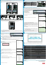
The principal components of the VSN 300 WIFI LOGGER CARD are shown in the figure and described in the following table:
Main components
A
Antenna connection cable
B
Antenna (RF Technology Corp. Model EA-79 F RP SMA)
C
Connection terminals
D
Power LED
E
Status LED 2
F
Status LED 1
G
Coaxial connector
H
Mechanical mounting bracket
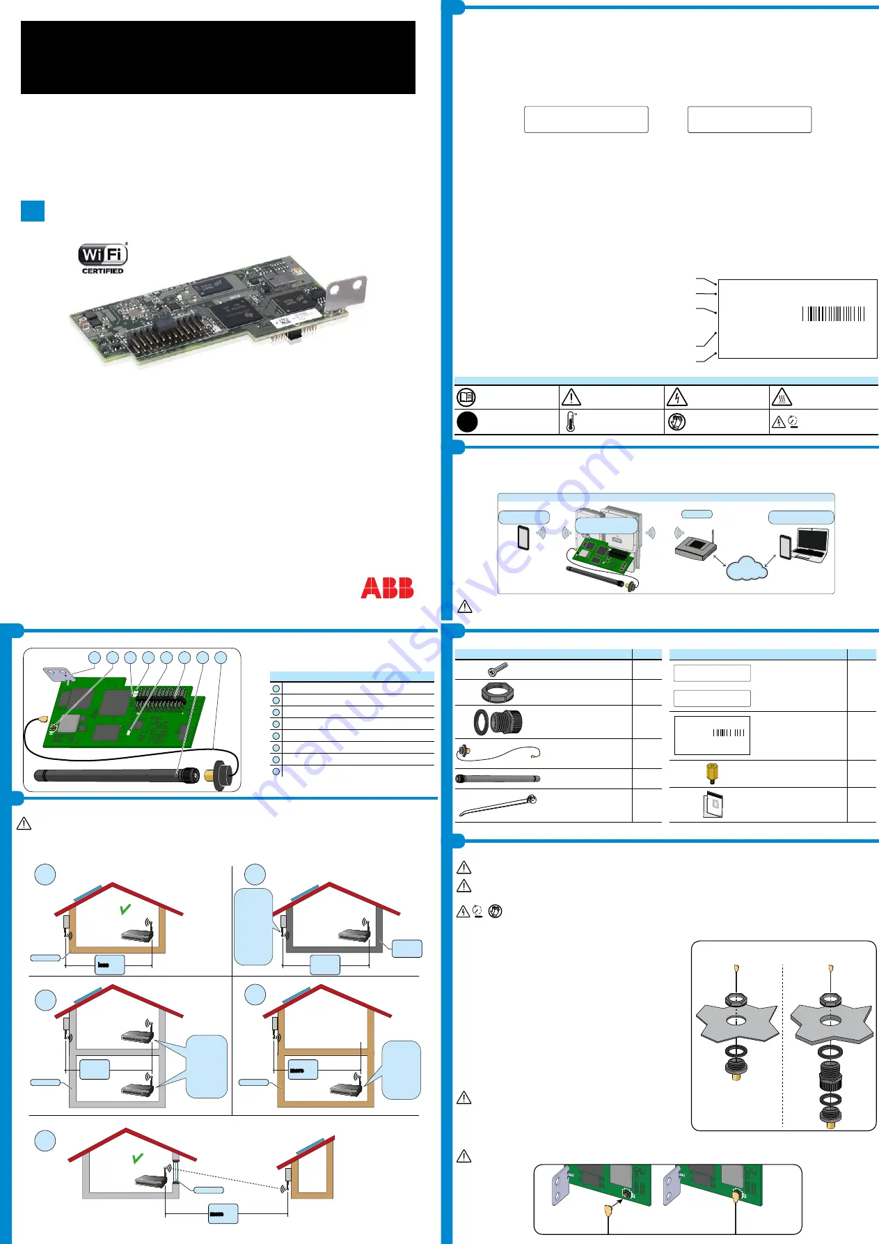
The communication among VSN300 WIFI LOGGER CARD and router is based on WiFi signal that could be limited by obstacles and distance.
The device must be kept away from large metal objects and electrical devices with strong magnetic field to ensure a good communication quality.
The radio signal level between WIFI LOGGER CARD and router can be increased in different ways:
1. Change the direction of the antenna.
2. Find a new location for the router taking care about the signal decrease due to materials through which the radio signal has to pass:
Before mounting the system it is important to consider the possible scenarios (see below) and evaluate the right position for Wi-Fi router.
1
2
3
5
4
?
?
NO
OK
OK
?
Distance
less
than
10mt/33ft
Distance
more
than
30mt/100ft
Distance
more
than
10mt/33ft
Wooden
Wooden
Window
Concrete
Metal or
reinforced
concrete
Any
distance
Any
distance
Install
the WiFi
antenna in
-
ternally using
an extension
cable or
evaluate the
possibility to
install a WiFi
repeater
Evaluate the
WiFi signal
quality and the
possibility to
install a WiFi
repeater
Evaluate the
WiFi signal
quality and the
possibility to
install a WiFi
repeater
The distances indicated in the below examples are between WIFI LOGGER CARD and the router.
“Before installing the VSN300 Wifi Logger Card it is strongly recommended to previously read both the present Quick Installation Guide (QIG) and the product
manual (available on ABB official web site www.abb.com/solarinverters.
The present QIG refers to VSN300 Wifi Logger Card in FW version 1.8.x on.
The VSN300 WIFI LOGGER CARD printed circuit board will be marked with the following information, identifying the product:
-
Manufacturer Mark/Trade Mark
-
CE (European Union) Marking
-
RCM (Australia) Marking
-
FCC ID
The FCC ID is FCC ID: X6W-3N16E when the VSN300 WIFI LOGGER CARD is assembled with a Wi-Fi radio module supplied by Epcos
The FCC ID is FCC ID: X6W-3N16M when the VSN300 WIFI LOGGER CARD is assembled with a Wi-Fi radio module supplied by Murata
A dedicated label including the FCC ID must be placed in a visible position on the exterior of the Inverter host equipment
Contains FCC ID: X6W-3N16E
Contains FCC ID: X6W-3N16M
FCC (Federal Communications Commission) WARNING
1. This device complies with Part 15 of the FCC Rules. Operation is subject to the following two conditions:
(1) this device may not cause harmful interference, and (2) this device must accept any interference received, including interference that may cause undesired
operation
2. This equipment has been tested and found to comply with the limits for a Class B digital device, pursuant to Part 15 of the FCC Rules. These limits are designed
to provide reasonable protection against harmful interference in a residential installation. This equipment generates, uses and can radiate radio frequency energy
and, if not installed and used in accordance with the instructions, may cause harmful interference to radio communications. However, there is no guarantee that
interference will not occur in any particular installation. If this equipment does cause harmful interference to radio or television reception, which can be determined
by turning the device off and on, the user is encouraged to try to correct the interference by one or more of the following measures:
-
Reorient or relocate the receiving antenna.
-
Increase the separation between the equipment and receiver.
-
Connect the equipment into an outlet on a circuit different from that to which the receiver is connected.
-
Consult the dealer or an experienced radio/TV technician for help.
3. RF Exposure. This device complies with Part 2.1091 of the FCC Rules for an uncontrolled environment. This equipment should be installed and operated with
a minimum distance of 20cm between the antenna and the user.
Refer to the specific section describing procedures how to integrate and use this device into the host fixed mount inverter.
Changes or modifications made to this equipment not expressly approved by the Manufacturer may void the FCC authorization to operate this equipment.
The identification label contained on the VSN300 WIFI LOGGER CARD box has information regarding the device and manufacturer.
In some cases on the equipment, dangerous or hazardous zones are indicated with signs, labels, symbols or icons.
Symbols and icons
Always refer to instruction
manual
General warning - Important
safety information
Hazardous voltage
Hot surfaces
IP65
Protection rating of equip-
ment
Temperature range
Always use safety clothing
and/or personal safety
devices
Time needed to discharge
stored energy
10
J1
U8
U3
U11
U7
J2
1
2
23
24
U8
U3
U11
U7
G
C B A
D
E
F
H
The VSN300 WIFI LOGGER CARD allows for connection of the inverter to a local LAN Wi-Fi network via a wireless connection.
The VSN300 WIFI LOGGER CARD features an integrated web server that enables establishment of a direct connection to a PC,smartphone or tablet, allowing
for board configurations and local monitoring of the inverter.
When the inverter is connected to the WLAN network with Internet access, the VSN300 WIFI LOGGER CARD allows for transfer of data to the Aurora Vision
®
Plant Management Platform for remote monitoring purposes over an Internet browser or Mobile App (Plant Viewer for Mobile)
APPLICATION WITH VSN300 WIFI LOGGER CARD
WI-FI router
INTERNET
POWER
ALARM
GFI
ESC
UP
DOW
N EN
TER
TRIO
TRIO
POWER
ALAR
M GF
I
ESC
UP
DOWN
ENTER
Aurora Vision
Plant Management Platform™
®
Aurora Vision
Plant Viewer for Mobile
J1
U8
U3
U11
U7
J2
1
2
23
24
VSN300
WIFI LOGGER CARD
In order to assure the correct operation of the card do not install other monitoring devices in addition to the VSN300 WIFI LOGGER CARD.
Installation without
adapter
Installation with
adapter
ABB
VSN300 WIFI LOGGER CARD
SN: YYWWSSSSSS
MAC: XX:XX:XX:XX:XX:XX
PRODUCT KEY: XXXX - XXXX - XXXX - XXXX
- Manufacturer name
- Model name
- Serial Number composed of:
YY = Year of production
WW = Week of production
SSSSSS = progressive number
- VSN300 WIFI LOGGER CARD Mac address
- Product Key composed of 16 characters used to activate the VSN300 WIFI LOGGER CARD
The package contains all the components required to correctly install and connect the VSN300 WIFI LOGGER CARD:
Main components
Quantity
Locking screw
1
Plastic lock nut
1
Adapter kit (gasket and
adapter)
1 + 1
Antenna connection cable
1
WIFI antenna
1
Cable Tie
1
Main components
Quantity
or
Contains FCC ID: X6W-3N16E
Contains FCC ID: X6W-3N16M
FCC ID label
1
ABB
VSN300 WIFI LOGGER CARD
SN: YYWWSSSSSS
MAC: XX:XX:XX:XX:XX:XX
PRODUCT KEY: XXXX - XXXX - XXXX - XXXX
Identification label
1
Standoff for installation on
inverters equipped with arc
fault device
1
In additio
n to what
is explain
ed in this
guide, th
e safety a
nd installa
tion inform
ation pro
vided in th
e installat
ion manu
al must be
read and
followed
.
The techn
ical docu
mentation
and the in
terface an
d manage
ment softw
are for th
e product
are availa
ble at the
website.
XXXXX
XXXXXX
XXXXXXXX
XXXXXXX
XXXXX
XXXXXXX
ABB solar
inverters
Technical documentation


