background image

 VSN700 Data Logger Product Manual 


13 - 

Configure the data logger 

The installer must use a laptop with an Ethernet cable to communicate directly to the data logger’s 

web-based user interface for configuration. The data logger’s web server has many options and 

capabilities, but here we only describe those necessary to get your system up and running. 
1.


Configure the laptop’s Ethernet port to obtain a Dynamic IP address automatically through 

DHCP; typically, laptops are already configured this way. 

2.


Connect the Ethernet cable between the secondary Ethernet port marked Eth1 on the data 

logger and the laptop computer.  

3.


Wait for the laptop to obtain an IP address from the data logger and then open an Internet 

browser window on the computer. Type in the following URL in the address bar. 


http://172.17.17.1


4.


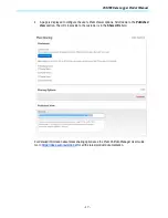
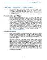
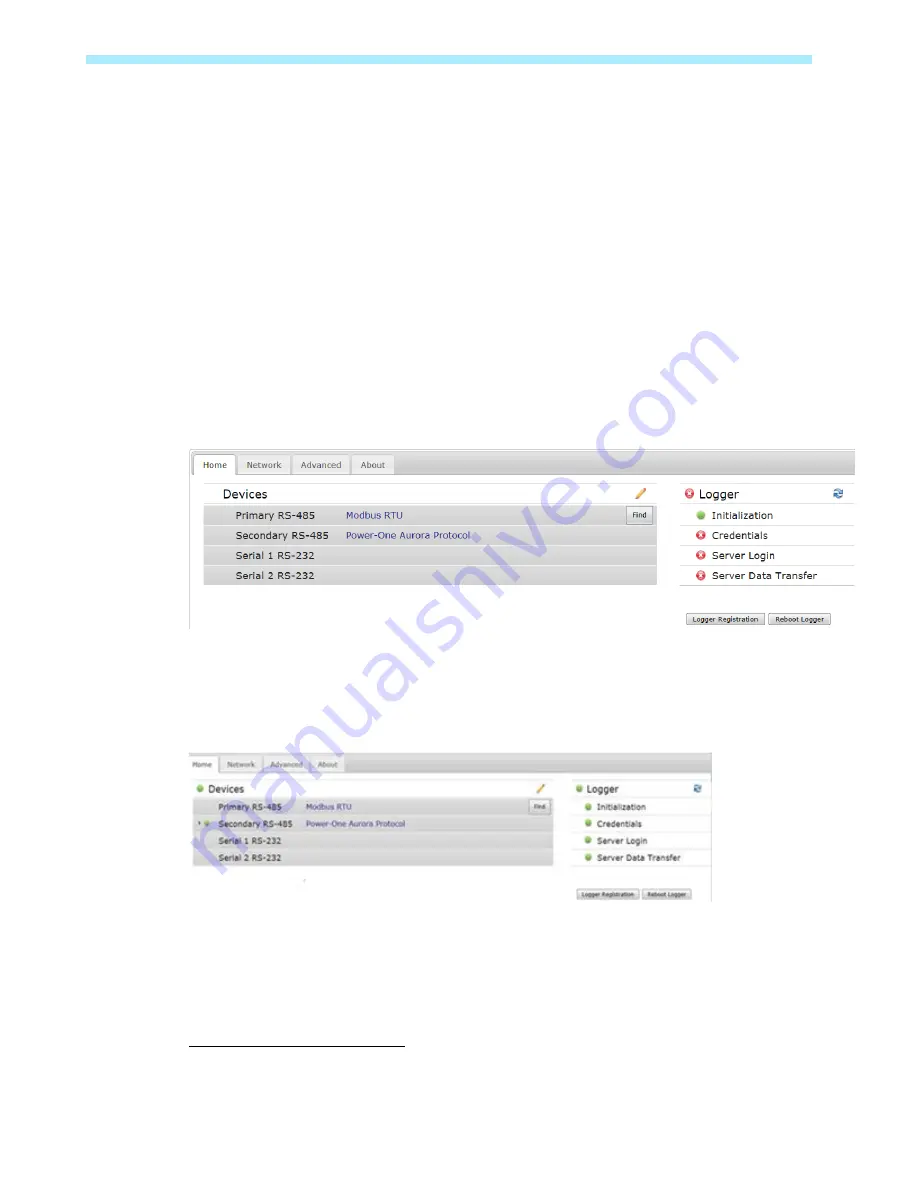
The following Home page (or similar

3

) will appear: 


Select the tabs across the top to perform configuration operations and select one of the ports in the 

Devices list to set up devices. 
Verify all the icons for the data logger in the status area to the right are green. It may take some 

time for all the icons to turn green. 


The MAC address (Logger ID) for the data logger is displayed at the top of the page. Be sure to 

write down the MAC address of the data logger. The MAC address is  needed later for Asset 

Registration. 


3

 Due to the constantly evolving nature of software, the images shown in this manual may be out of sync with the 

current user interface. The options mentioned should still be accessible, but may be renamed or accessed in a 

different way than is described in this manual.  

Summary of Contents for VSN700

Page 1: ...ABB solar monitoring Product manual VSN700 Data Logger ...

Page 2: ...lable at all times to everyone who interacts with the equipment Symbols and signs In the manual the danger or hazard zones are indicated with signs labels symbols or icons Generic hazard Important safety information This points out operations or situations in which staff must be very careful Hazardous voltage This points out operations or situations in which staff must be very careful due to hazar...

Page 3: ...t deterioration resulting from transportation or particular environmental conditions performing maintenance incorrectly or not at all tampering or unsafe repairs use or installation by unqualified persons ABB will NOT be held responsible for the disposal of displays cables batteries accumulators etc The Customer shall therefore arrange for the disposal of substances potentially harmful to the envi...

Page 4: ...wer access for end users 15 Adding an ABB weather station 18 Configuration for a weather station device 19 Interfacing VSN700 05 with SCADA systems 21 Power One SunSpec Adapter 21 Modbus TCP server 21 Data logger configuration for SCADA or other monitoring systems 22 Set a Static IP Address for the data logger 22 Configure the serial interfaces 22 Communication with devices by SCADA or monitoring ...

Page 5: ...ternet connected device The installer logs on to the Aurora Vision website to register the VSN700 series data logger and ensures that the logger is correctly passing information to the servers The installer provides a URL to the end user for access to Aurora Vision Plant Viewer The installer can also monitor all of their sites through a web browser using Aurora Vision Plant Portfolio Manager The V...

Page 6: ... through a router to get access to the Internet In summary any kind of Internet connection will work VSN700 Data Logger models The data logger comes in three models The feature differences are provided in the table below Model Supported Devices and Features Residential VSN700 01 XX Monitor up to 5 ABB or legacy Power One single phase and or small three phase Trio 5 8 7 5 8 5 string inverters Comme...

Page 7: ...ructions are for use by qualified personnel only To reduce the risk of electric shock do not perform any servicing other than that specified in the operating instructions unless you are qualified to do so Preparation Make sure you have the following tools and materials prior to starting installation Tools Standard Electrician s Toolkit Personal Protective Equipment Gloves Goggles Clothing Material...

Page 8: ...ion Refer to your inverter manual for information on terminal locations and daisy chaining inverters Use RS 485 data wire with one twisted pair one ground conductor and a shield with drain wire Belden 3106A or equivalent DO NOT USE CAT5 6 CABLE FOR THE RS 485 DATA WIRE 5 For systems with multiple inverters the RS 485 network must be terminated at the final inverter by a switch near the RS 485 term...

Page 9: ...er Station for information on connections for an attached weather station RS 485 Connection Data Logger RS 485 Screw Terminal Connector Example Inverter RS 485 Pin Label RS 485 Negative 1 TR Port 5 RS 485 Positive 2 TR Port 4 RS 485 Negative 3 RS 485 Positive 4 Ground 5 RTN Port 3 VDC Power Only 6 PVI xxxx Indoor Series PVI x x Outdoor Series PVI x x Outdoor Series U S Termination Switch Eth0 For ...

Page 10: ...7 2VA The logger will typically only consume about 3VA during normal operation 8 For models with an AC DC adapter connect the adapter to a standard power outlet The power supply accepts a Universal AC input for use worldwide and will come with a plug adapter that is specific for your region An appropriate travel adapter can be used if connecting to a different socket type 9 Check the data logger s...

Page 11: ...on Commercial data loggers Modbus devices are not supported by the Residential data logger The RS 485 ports on the Max version data logger are configurable for either protocol In any case all inverters connected in a daisy chain must use or be configured to use the same communication protocol and protocol settings For systems with multiple inverters each inverter in a daisy chain must be manually ...

Page 12: ...can be used for detecting network link and network traffic Eth0 LED GREEN Link Eth0 LED GREEN BLINK Traffic Eth0 LED OFF No network link If no activity is seen on the LEDs double check all connections ABB recommends a wired Internet connection because it is more reliable and requires less setup If it is necessary to connect to a wireless network a wireless network bridge with an Ethernet port is r...

Page 13: ...open an Internet browser window on the computer Type in the following URL in the address bar http 172 17 17 1 4 The following Home page or similar3 will appear Select the tabs across the top to perform configuration operations and select one of the ports in the Devices list to set up devices Verify all the icons for the data logger in the status area to the right are green It may take some time fo...

Page 14: ...sing a Max version VSN700 For the Secondary RS 485 connection once legacy Power One inverters and ABB inverters using the Aurora Protocol are properly addressed and wired in the RS 485 daisy chain inverters will automatically be discovered and displayed Set a static IP address Setting a Static IP is only necessary if required by your network In almost all cases you can skip this section 1 Obtain S...

Page 15: ... Aurora Vision User ID and password with Administrator privileges From the data logger s user interface click the Logger Registration button to go to the Asset Registration on the Administration page of Portfolio Plant Manager If you are not using the data logger s web based user interface go to https admin auroravision net customeradmin Select Administration Register Logger and type in the MAC ad...

Page 16: ...VSN700 Data Logger Product Manual 16 2 Select the Plant from the asset list in the screen area to the left 3 Once the correct Plant is displayed select Share from the Actions menu ...

Page 17: ... Viewer options Scroll down to the Published View section The URL to provide to the customer is in the Share URL field For detailed information about plant sharing options see the Plant Portfolio Manager User Guide Go to https docs auroravision net for all the latest product documentation ...

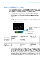
Page 18: ... Data Logger RS 485 Screw Terminal Connector Example Inverter RS 485 Pin Label Example VSN800 XX RS 485 Pin Label RS 485 Negative 1 TR Terminal 5 RS 485 Positive 2 TR Terminal 4 RS 485 Negative 3 RS 485 A RS 485 Positive 4 RS 485 B Ground 5 RTN Terminal 3 RS 485 GND and GND VDC Power Only 6 N A 24VDC 3 The VSN800 weather stations can tap the power terminals on the data logger for its power source ...

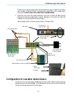
Page 19: ...e data logger Wire the weather station to the data logger as shown in the figure below Configuration for a weather station device The Devices list on the data logger s Home page will show all the different devices connected through all the ports on the data logger It is essential that the devices you set up here match how devices are physically connected to your data logger To Network via Switch o...

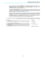
Page 20: ...he data logger s web interface in the same manner as for configuring inverters connect an Ethernet cable from the data logger s Eth1 port to a laptop and go to http 172 17 17 1 To add the VSN800 weather station go to the Home tab and push the Find button for the Primary RS 485 port Click on Start in the window that pops up to begin the device discovery process The default Modbus address for the VS...

Page 21: ...ched in SunSpec Modbus maps when using the data logger s SunSpec adapter Modbus RTU device data maps are not converted or cached For complete SunSpec specifications and open information standards go to http www sunspec org specifications Modbus TCP server External monitoring or SCADA systems must communicate with the data logger using Modbus TCP The data logger s Modbus TCP server gateway converts...

Page 22: ...ow for better polling performance however advanced features like remote inverter firmware upgrade are only available through the Power One SunSpec Adapter option In the Home tab click the pencil icon and use the drop down menus to configure the Primary and Secondary RS 485 interfaces based on the type of devices connected to these ports Polling performance is better if half of the devices are conn...

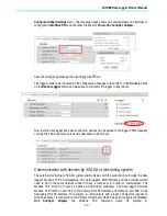
Page 23: ...y described in this manual Communication with devices by SCADA or monitoring system The external monitoring or SCADA system communicates with the serial devices through the data logger s Modbus TCP server gateway The data logger s Eth0 interface and the external system need to be on the same network subnet or have a route set up in order to communicate The Modbus TCP ports must also be opened as d...

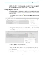
Page 24: ... can be auto discovered using the Find button 1 Go to the Home tab Click on the Pencil icon across from Devices The following screen appears 2 The screen shows the current configuration settings for each port To add a device select the Plus button on the RS 485 port that the device is connected to A window appears to enter device settings 3 Select the Device Type from the pull down menu 4 Set the ...

Page 25: ...P based devices through the Eth0 and or Eth1 interfaces The Modbus TCP interface must first be enabled by clicking the pencil icon and then using the dropdown menu for the Modbus TCP interface to enable it The logger must be rebooted after applying this change Add devices to the Modbus TCP interface similar to how devices are added to the other device interface s The type of device its IP address ...

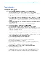
Page 26: ...e end of the cable should be connected to Eth1 and the other to your computer s Ethernet port You should see a link LED illuminated for both the data logger and the computer 3 Verify the Network settings on the computer The Network settings for the Ethernet connection should be set to DHCP Automatically obtain an IP address Try to Repair or release renew the network connection on the computer 4 If...

Page 27: ...lit when powered is an indication that the logger is not running properly and may need replacement if the problem persists Press the Reset button closest to the corner of the data logger to reboot the unit You need to wait until the logger is fully rebooted and then check to see if data is being transmitted correctly to see if this fixes the problem If problems persist you may need to restore the ...

Page 28: ... name Problem description Be prepared to describe the problem you are experiencing including specific details of the application installation and any additional pertinent information In the event that the equipment needs to be returned to the factory for any reason please call to obtain a RMA number Return Merchandise Authorization Do not return items without a RMA number displayed on the outside ...

Page 29: ... inverters VSN700 Commercial Up to 10 ABB or legacy Power One string inverters and one ABB weather station String inverters can be single phase or three phase VSN700 Max All ABB or legacy Power One solar inverters 3rd Party devices and other ABB devices are also supported consult the latest supported devices list for an up to date list USB 2 0 Ports The USB Ports are currently not used Hardware CP...

Page 30: ...3 Tcp udp The data logger must be able to resolve domain names to ensure scalability and dynamic changes on the Internet DNS required Out https 443 Tcp As an HTTP client the data logger uses SSL TLS protocol connections to Aurora Vision servers for secure communication The logger uses this port for all services including data transmission firmware upgrade configuration management and remote comman...

Page 31: ...ess of how the logger is configured the following information is required Configuration Purpose IP Address Allows the logger to take part in the local network This does not need to be a public IP address In most cases this is a private IP address Subnet mask Used to determine if two computers are on the same network Gateway The IP address of the computer which will forward network traffic from the...

Page 32: ...VSN700 Data Logger Product Manual Contact us www abb com solar YOUR ABB DISTRIBUTOR SOLIGENT 800 967 6917 www soligent net ...

Reviews: