VSN730 System Monitor Product Manual
-
11 -
Cable requirements
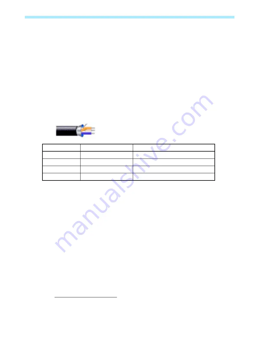
RS-485 data terminals can accept stranded copper wire of size #16-#24 AWG. ABB recommends
stranded copper size #18-#22 AWG with a twisted-pair of conductors, a signal return (common)
conductor, and a shield with drain wire. Belden 3106A or equivalent cable is recommended. Do not
run the remote device data cable next to large current carrying conductors. If the cable used has
multiple twisted-pairs, then one twisted-pair should be shorted together for the signal return wire.
The recommended RS-485 cable requirements are listed below:
•
Cable must be rated for RS-485 by the manufacturer
•
Cable must be shielded to at least 90% coverage
•
Cable must have nominal impedance between 100-150 ohms
•
Cable must have at least one twisted-pair
•
Cable must have a third conductor for signal return or common (signal ground)
Three-Wire Belden 3106A Cable
RS-485 Wire
Belden 3106a Wire Color
System Monitor Connection Point
RS-485 Positive
Orange/White stripe
Citel, top tier, left terminal
RS-485 Negative
White/Orange stripe
Citel, top tier, right terminal
Signal Ground
Blue/White stripe
Citel, bottom tier, left terminal
Cable Shield
-----
Citel, bottom tier, right terminal
Inverter address configuration
For systems with multiple inverters, each inverter must be manually assigned a different RS-485
address. Refer to the inverter manual(s) for instructions on how to set inverter addresses and exact
inverter connection points. Write down the serial number and RS-485 address for each inverter so
you can determine which inverter is which on the monitoring system.
Daisy chain termination
For systems with multiple devices, the RS-485 network must be terminated at the final inverter or
device by a 120 Ohm resistance across the D+ and D- conductors to minimize signal reflection due
to impedance mismatch. ABB inverters have a switch on their communication boards for setting the
termination resistance. The farthest inverter in the daisy chain must be terminated by setting the
inverter termination switch to ON. For all other inverters or devices in the daisy chain, turn OFF the
termination switch. Refer to the inverter(s) or device’s manual for location(s) of the RS-485
termination switch.
2
In some environments you may experience poor RS-485 signal quality due to noise. If signal quality is a
problem, double-check that the last inverter in the chain is terminated and other inverters are not terminated. If
problems persist, it may prove helpful to attach
a 120 Ohm 0.5 Watt resistor across the D+ and D- screw terminals
on the data logger.


