ABB Turbocharger VTR..4
Seite / Page 7
Ausserbetriebnehmen
Kap. / Chap. 6
Taking out of operation
ABB Turbo Systems Ltd
10013
- A -
)**
1.2
Turbinenseitig blockieren
Hinweis
Blockiervorrichtung gesondert bestellen.
1.2.1
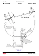
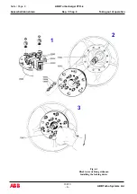
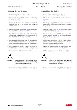
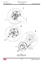
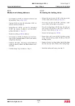
Blockiervorrichtung einbauen
Hinweis
Die Vorschriften des Motorenherstellers
sind zu beachten.
Das gilt besonders für das Unterteilen des
Spülluftreceivers und der Leistungs-
reduzierung einzelner Zylinder.
Vorsicht!
Kühlwasser nur abstellen, wenn das
Turbinengehäuse stark undicht ist und
damit den Betrieb des Motors gefährden
könnte.
Wird die Turbine eines blockierten Turboladers weiterhin
von Abgasen durchströmt, muss durch den Verdichter Luft
zirkulieren, damit er sich nicht zu stark erwärmt.
Es reicht dabei aus,wenn die Luft durch den stillstehen-
den Turbolader hindurch angesaugt wird.
Sind mehrere Turbolader an eine gemeinsame Ladeluft-
leitung angeschlossen, verhindert das Abschliessen des
Luftaustrittsflansches am blockierten Turbolader, dass Luft
wegströmt.
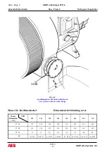
Das Verdichterrad wird gekühlt, wenn in der Ab-
schlussplatte am Luftaustrittsflansch
"dc" verhanden ist.
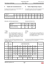
Die Abschlussplatte kann anhand der Tabelle auf Seite 6
selbst gefertigt werden.
1.2
Locking the turbine end
Note
Order the locking device separately.
1.2.1
Installing the locking device
Note
Be careful to observe the manufacturer’s
instructions.
This applies especially for partitioning the
scavenging air receiver and the power
reduction of individual cylinders.
Caution !
Shut off the cooling water only if the
turbine casing is leaking strongly and thus
represents a hazard for the operation of
the engine.
If exhaust gases continue to flow through the turbine of a
locked turbocharger, air must circulate through the
compressor so that it does not get too hot.
It is sufficient if the air is drawn through the shut down
turbocharger.
If a number of turbochargers are connected to a joint
charge-air receiver, locking the air outlet flange on the
locked turbocharger prevents the escape of air.
The compressor wheel is cooled when there is a hole "dc"
in the cover plate on the air outlet flange
The blanking cover can be manufactured by yourself
according to the table on page 6.
Summary of Contents for VTR184-21
Page 1: ...Operation Manual VTR184 11 21 ZTL2106 Turbocharging ABB Turbo Systems Ltd...
Page 4: ......
Page 5: ...0 Preliminary remarks Vorbemerkungen...
Page 6: ......
Page 18: ......
Page 19: ...1 Instructions on safety and hazards Sicherheits und Gefahrenhinweise...
Page 20: ......
Page 34: ......
Page 35: ...2 Putting into operation Inbetriebnehmen...
Page 36: ......
Page 53: ...3 Operation and maintenance Betrieb und Unterhalt...
Page 54: ......
Page 99: ...Troubleshooting Beheben von St rungen 4...
Page 100: ......
Page 107: ...Disassembly and assembly Demontage und Montage 5...
Page 108: ......
Page 162: ......
Page 163: ...Taking out of operation Ausserbetriebnehmen 6...
Page 164: ......
Page 180: ......
Page 181: ...Appendix Anhang 7...
Page 182: ......
Page 184: ...10021 ABB Turbo Systems Ltd E Seite Page 2 ABB Turbocharger VTR 4 Anhang Kap Chap 7 Appendix...
Page 228: ......
Page 229: ...Approved lubricating oils Zugelassene Schmier le 8 1...
Page 230: ......
Page 234: ......
Page 236: ......
Page 237: ......
Page 238: ...ABB Turbo Systems AG Bruggerstrasse 71a CH 5400 Baden Switzerland ABB...

