background image

Installation and Maintenance Manual


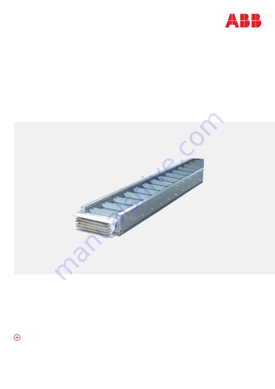
WavePro LT Aluminium Busway

•  Unparalleled safety and protection 

measures

•  Wide range of designs meeting cus-

tomer’s stringent requirements

•  Lower installation and maintenance 

costs

Summary of Contents for WavePro LT

Page 1: ...llation and Maintenance Manual WavePro LT Aluminium Busway Unparalleled safety and protection measures Wide range of designs meeting cus tomer s stringent requirements Lower installation and maintenance costs ...

Page 2: ...em provides safe and reliable electrical distribution in commercial and industrial applications WavePro LT Busway System reduces installation cost while providing superior performance for electrical contractors and end users ...

Page 3: ...nfiguration 008 020 Installation 008 012 Busway Installation 013 014 Installation of bus plug 014 Installation of end box 015 Installation of the joint 016 019 Installation of the Spring Hanger 020 Installing IP54 IP65 busway 021 Commissioning 022 Maintenance 023 024 Busway installation checklist ...

Page 4: ...ry with respect to and assumes no responsibility for the accuracy completeness sufficiency or usefulness of the information contained herein No warrantees of merchantability or fitness for purpose shall apply To ask questions about your installation contact the ABB company at 86 800 820 8206 Warning Warning notices are used in this publication to emphasize that hazardous voltages currents or other...

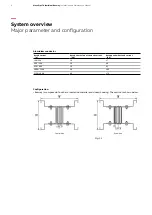
Page 5: ...ture within 24 hours should not be greater than 35 There is no obviously shaking and impact vibration at this site The air should be free from explosive risk metal corrosion insulation damage due to gas or dust There should be no rain or snow invading in site Major parameter and configuration Storage Notice Rated working voltage 690V 415V Rated insulation voltage 1000V 690V Rated working current 1...

Page 6: ...uminium conductor Rated current A Rated short time withstand current kA Rated peak withstand current kA 100 250 10 17 400 500 20 40 630 800 30 63 1000 2500 50 105 3150 4000 80 176 Configuration Busway is composed of bus bars insulation material and closed housing The section is shown below four wires five wires Fig 1 1 ...

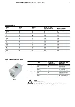
Page 7: ...0 128 218 22 7 24 3 2000 128 258 26 9 29 0 2500 128 316 32 2 34 9 3150 128 460 48 0 51 9 3800 128 550 57 9 62 8 4000 128 590 62 3 67 6 Current Weight Kg Only with switch Physical data of plug L W H mm Manual operating mechanism 100 160A 25 450 240 260 250A 30 550 260 280 400A 40 650 300 300 1000A 85 1200 550 400 Rotary operating mechanism 100A 160A 25 430 240 275 70 250A 30 550 260 320 70 400A 40 ...

Page 8: ...ified with an item number label Make sure to install all the busways according the blueprint unless the engineer instructs locally All the screw down moment should according to below form excepting the bolt in the joint Caution Inspect each busway piece for possible damage or contamination Contact surfaces must be clean However do not attempt to polish tarnished contact surfaces Check to ensure th...

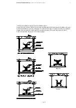
Page 9: ...as to inlay steel expansion bolts holes may also be drilled on the spot for flexible installation or pre bury steel object for welding with hangers The distance between two adjacent hangers shall not exceed 2m Please specify your special requirements in order There are two forms of horizontal installation Please refer to the following figure Fig 2 2 Edgewise Flatwise ...

Page 10: ...ertical and horizontal installation Key points in horizontal installation When busway is placed horizontally its distance from ground should be more than 2 2m except for those in electricity dedicated rooms e g distribution room electromotor room electric shaft room interlayer etc The distance from wall should be more than 0 1m and that from upper floor ceiling floor and beam bottom should not be ...

Page 11: ... or more than two vertical runs of busway installed in the same silo Please refer to the Fig below Fig 2 4 When choosing the spring hangers the elastic force should be adjusted to G F kilogram G is the weight of busbar between each floor while F is 5 10 kilograms which refer to the on site condition There are mainly three types of installation A Two types for front installation of spring hangers P...

Page 12: ...an 0 7m while distance between busway and wall backwards should be more than 0 1m Busway installed in riser should be reinforced in the center generally when the space between floors exceed 4m or according to the user special requirements which may be carried out referring to the figure The additional supporters is related with busway rating In vertical installation spring bracket should be instal...

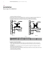
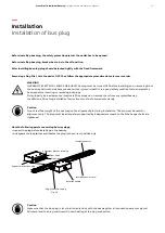
Page 13: ...from the busway Failure to do so may cause serious injury or death It is a good safety practice to de energize the busway before inserting or removing bus plugs Only properly trained personnel may install bus plugs on or remove them from energized busway In addition all bus plug installation instructions must be followed completely Caution Do not rest the weight of the bus plug on the alignment pi...

Page 14: ...n riser maybe carried out referring to the Fig 2 9 Installation of the joint The joint uses double headed break off bolt It has a intension tag which helps to notice the position Fig 2 9 Fig 2 10 Make the two busway face to face and put apart 40 50mm between them Insert the joint between the two busway and screw down the bolt until the first cap be cutted and the tag drop The standard torque is 62...

Page 15: ...on work interrupted all the joint and busway ends should be covered by plastic to prevent it form water or dust Notice Don t use extreme force when inserting the joint Please use a wood or rubber mallet to hit it when needed Never use a steel hammer or other hard object to assist the installation Fig 2 11 Fig 2 12 Fig 2 13 ...

Page 16: ...y The width of the angle steel is consistent with the height of busway please refer to the Page 5 table 1 and table 1 1 Suspend the busway ensuring the distance from the center of busway joint to the floor is 560mm According to the figure 2 14 ensure the fixed size of 178mm fix double headed bolt to the channel steel then put the spring and set the spring hanger Fix the spring hanger to the buway ...

Page 17: ...WavePro LT Aluminium Busway Installation and Maintenance Manual 17 Fig 2 14 ...

Page 18: ...18 WavePro LT Aluminium Busway Installation and Maintenance Manual Fig 2 14 1 Drilling hole Installation Installation of the Spring Hanger ...

Page 19: ...WavePro LT Aluminium Busway Installation and Maintenance Manual 19 Assembly drawing of Spring hanger Fig 2 14 2 Table 3 ...

Page 20: ...ent PC cover need be used to clip on Joint clamp plate to protect joint bolts from water For IP65 busway it is required to use silicone gel CSL588 to seal the gap between Joint clamp plate and housing grounding plate The busway protection level is only rated when installation completed and it installed properly GE recommends to set and tighten joints at the nominal length and sealing each joint ac...

Page 21: ...shall be not less than 0 5 MΩ If the insulation resistance is within 0 1 MΩ 0 5 MΩ the busway can operate at no load for 4 16 hours and then check insulation resistance again If the insulation resistance is less than 0 1 Ω the busway shall not be energized The busway system should be subject to electrical test before being energized All connection equipment of the system should be associated prope...

Page 22: ...temperature rise with infrared thermal scanning equipment Check insulation resistance of the busway system and keep a complete record Make sure the installation bracket is stable and the reliable connection of the joint bolt Check if there is any rust or corrosion with components replacement is necessary Check the equipment close to busway that might cause damage because of external heating Clean ...

Page 23: ...s infinite resistance 6 Mounting and support a Is each 10 feet of bus run supported including any vertical sections Closer supporting may be required based on job specifications b Does any support interfere with a bus joint c Are any bus terminations to other equipment used as support Busway weight should not bear on equipment such as switchgear switchboards or transformers 7 Is the bus installed ...

Page 24: ...is run of bus This checklist is intended to insure a sound installation of WavePro LT busway It is not intended to cover all items related to the installation successful startup and long term use of the product and in no way relieves the contractor of his obligation to meet all specification and code requirements Installation Contractor Signed Date Busway installation checklist ...

Page 25: ......

Page 26: ...1SXH3432006_EN Rev A 06 2020 SH HG ABB Ltd Distribution Solutions Electrification P O Box 8131 CH 8050 Zurich Switzerland abb com contact ...

Reviews: