50
2
5
x45
6
1
9
3
°
3
°
1
4
3°
3°
44
1
x
4
5
GUID-4B194DC1-C58E-4C47-8A13-9F4F703018D1 V1 EN
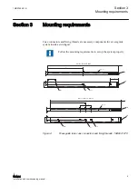
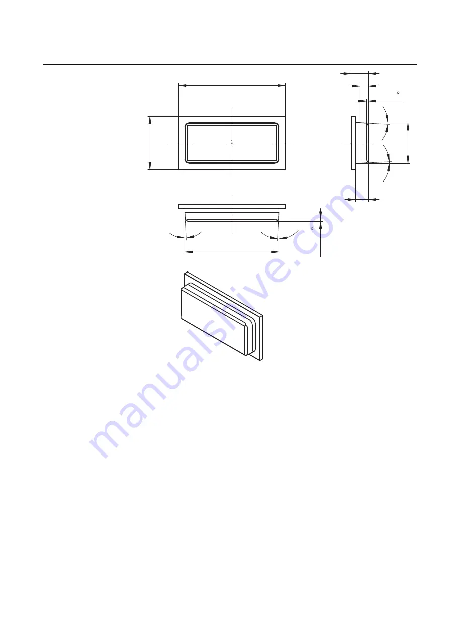
Figure 4:
End cover for the waveguide tube, 1VB8001476
3.1
Horizontal displacement
The wireless communication system works properly with the horizontal
displacement of Z < 5 mm between the waveguide tubes. Larger gaps are not
allowed because the transmitting power should be limited to 0 dBm.
1MRS755551 B
Section 3
Mounting requirements
WGA631
11
Installation and commissioning manual

