background image

16

 | XSERIES G5 | 2106026MNAA


1.2.4


XSeries

G5

 calculation methods 

The records and statistics generated are based on the following calculation methods of the XSeries

G5


Calculation of flow rates and volumes is in accordance with AGA 3-85, AGA 3-92, AGA 3-2012, 
AGA-7 or ISO-5167. 


Calculation of the flow rates and volumes is in accordance with AGA-8 92 Gross or Detail or 
NX-19 Supercompressibility Standards. 


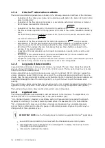
Calculation of the flow integral for the AGA 3-92 equation is: 

77

.

459

Tf

SP

DP

, once per second. 


The flow extension reported for the log period is the total of the volume calculation divided by 
3600.  
The total volume calculation period extensions are the sum of one second extensions. Each 

one second extension is: 

77

.

459

Tf

SP

DP


Calculation of the flow extension for the AGA 3-85 equation is: 

SP

DP

*

, once per second. 


Extrapolation of the flow accumulation during transducer calibration or calibration checks 
using the values for DP, SP and temperature at the time of entering Calibration mode. 


DP, SP and Tf are dynamic factors. Calculations that use these factors are based on the 
average of one second samples.  


Snapshots of the last calculation period inputs and calculation results can be used to verify 
calculation. 


Monitoring of the operational limits (minimums and maximums) to ensure detection and 
reporting of malfunctions or abnormal site conditions 


Acceptance and storage of system constants from PCCU32 or remote communication protocols 


The number of log records, daily records and events is user-configurable. 

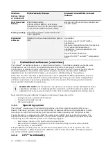
1.2.5


Log period data records 

Log period data entries are made every 60 minutes, by default. The user may change this period to 
any one of seven (7) choices (1, 2, 5, 10, 20, 30, or 60 minutes). The log period must never be less 
than the volume calculation period.  
Volume calculation period entries are made every second, by default. API 21.1 strongly suggests a 
volume calculation period (QCP) of once per second. The volume calculation period should never be 
greater than the log period and should be evenly divisible into the log period. Volume calculations are 
completed following the top of the current period (i.e., top of the hour, top of the minute, each 
second).  
The event/change, alarm, and system logs provide event, error, or alarm messages logged by active 
applications or by the system. These files are stored with the running configuration data (tfData). 
The number of log records, daily records and events is user-configurable. 

1.2.6


Applications  

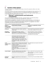
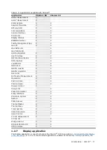
The following applications are available to add and activate to the XSeries

G5

. The applications are 

identified for use in the United States (US) or they are selectable (SU). 
*US - Standard System: standard or customary system of measurement (also called the English, 
Imperial or American) is the most commonly used system of measurement in the United States. 
*SU 

 Selectable Units: pressure controllers and pressure transducers have dedicated pressure 

sensors that are referenced to absolute, gauge or differential pressure. Engineering units may be 
changed within these pressure types. 


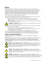
IMPORTANT NOTE:

 Use the following steps to determine supported XSeries

G5

 applications. 


Launch PCCU and click Entry to connect with the XSeriesG5 device in Entry mode.  


Click Application/License Management>Credit/App Info to display the most up-to-date 
XSeriesG5-supported applications.  


Click Help for additional information. 

Summary of Contents for XFC G5

Page 1: ... ABB MEASUREMENT ANALYTICS 2106026MNAA XSeries G5 User Manual XFCG5 XRCG5 Accurate reliable capable of measuring and monitoring gas flow to AGA it is API and ISO standard Measurement made easy ...

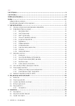
Page 2: ...es 19 1 2 10 Licensing 19 1 2 11 Additional features 19 1 3 Hardware overview 20 1 3 1 Enclosures 20 1 3 2 Liquid Crystal Display LCD assembly 20 1 3 3 Integral multivariable XIMV assembly 20 1 3 4 Electronic board 21 1 3 5 Communication connections 21 1 4 User interface software description PCCU32 23 1 5 Power supply equipment 23 1 5 1 Battery and charger power configurations 24 1 5 2 External po...

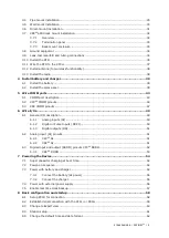
Page 3: ...5 3 XRC COMM pinouts 47 6 Wire I Os 49 6 1 General I O description 49 6 1 1 Analog inputs AI 50 6 1 2 Digital or Pulse Inputs DI PI 50 6 1 3 Digital outputs DO 51 6 2 Analog input AI pinouts 51 6 2 1 XFCG5 AI 51 6 2 2 XRCG5 AI 51 6 3 Digital input and output DI DO pinouts XFCG5 DI DO 52 6 3 1 XRCG5 DI DO 53 7 Powering the Device 54 7 1 Super capacitor charging at boot time 54 7 2 Power on sequence...

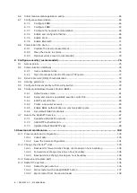
Page 4: ...Control RBAC 81 9 6 1 Default access roles 81 9 6 2 Setup and create a new RBAC security control file 81 9 6 3 Edit the security file 83 9 6 4 Create a new user account 83 9 6 5 Enable RBAC authentication on communication ports 84 9 6 6 Use default RBAC credentials 85 9 7 Secure the SSH SFTP service 87 9 7 1 Supported SSH SFTP accounts 87 9 7 2 SSH SFTP authentication 87 9 7 3 Update default SSH S...

Page 5: ...only 121 11 Calibration 122 11 1 Measurement pressure checks and calibration 122 11 1 1 Static pressure checks 122 11 1 2 Differential pressure checks 123 11 1 3 Calibrating static pressure 125 11 1 4 Calibrating differential pressure DP 126 11 2 Zero transducer 127 11 2 1 Static pressure 128 11 2 2 Differential pressure 128 11 3 RTD calibration 128 11 4 Resistance temperature detectors RTD bias 1...

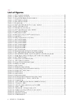
Page 6: ...CG5 DI PI DO terminals and input mode switches 52 Figure 6 4 XRC DI PI DO terminals input mode switches and debounce jumpers 53 Figure 7 1 XFCG5 Display startup messages part numbers are examples 54 Figure 7 2 XFCG5 BATT connector 55 Figure 7 3 Reset button and coldboot button 55 Figure 7 4 XFCG5 charger connection 56 Figure 7 5 Connect the external power supply 56 Figure 7 6 Battery and switch 57...

Page 7: ...19 Enable the SSH SFTP service 94 Figure 9 20 Enable and configure Ethernet Network Adapter 94 Figure 9 21 FileZilla Site Manager connection setup 95 Figure 9 22 Type private key passphrase password 96 Figure 9 23 FileZilla New Site window 96 Figure 9 24 Open the Flash AppData ssh directory 97 Figure 9 25 Upload public key from laptop to device 97 Figure 9 26 Verify public key upload is complete 9...

Page 8: ...e 11 3 Calibration equipment connection to XRCG5 AI 131 Figure 11 4 XRCG5 AIs 132 Figure 11 5 XRCG5 AIs and mode selector jumpers default setting 132 Figure 11 6 AI voltage default calibration values 133 Figure 11 7 Low calibration value for voltage 134 Figure 11 8 Calibrated AI example voltage mode 134 Figure 11 9 AI current default calibration values 135 Figure 11 10 Low calibration value for cu...

Page 9: ...alog input AI mode and range 50 Table 6 3 XSeriesG5 pulse input mode and debounce capabilities 50 Table 6 4 XFCG5 AI Pinouts 51 Table 6 5 XRC AI Pinouts 52 Table 6 6 XFCG5 DI PI DO pinouts 52 Table 6 7 XRC DI PI DO Pinouts 53 Table 8 1 Cables required for local communication 58 Table 8 1 Required station setup 61 Table 8 2 Communication setup parameters 66 Table 8 3 RS 485 Termination on COMM1 66 ...

Page 10: ... XSeriesG5 XFCG5 XRCG5 Quick Start Guide QSG 2106141 XSeriesG5 Startup Guide for XRCG5 and XFCG5 SUG 2106001 XSeriesG5 Board Replacement Kit Guide 2106079 Product Return Policy Information AKK106713A7549 2600T Series Pressure Transmitters 266 MODBUS Multivariable Transmitter 2105216 Wi Fi Antenna Kit 2106123 TFIO Module User Manual 2101226 User Drawings Document number XFCG5 Generic Pinout 2106114...

Page 11: ...to be installed The recommendations for safe working in the case of installation in an SIL loop The device can be operated at high levels of pressure and with aggressive media Serious injury and or considerable material damage can be caused if this device is handled incorrectly Ensure compliance with the regulations applicable in the country of use when working with the device The following conven...

Page 12: ...ring installation calibration or following damage to the pipeline Only properly trained and authorized personnel should work in hazardous locations There are no chemical or burn hazards Personal Protection Equipment is not required WARNING Bodily injury Apply power only after the procedures are complete Technicians must perform the procedures in order plan install wire verify the power on sequence...

Page 13: ... compatibility retained features Enclosure Enclosure doors looks updated aesthetic change only Same models and configurations identical form factor available per device type Electronic board design Updated microprocessor includes supercapacitor for persistent memory backup in the event of power removal loss Same form factor common and device specific board components and interfaces on same locatio...

Page 14: ...of applications enabled in each device type will vary depending on the site scenario The following sections describe device specific functionality and typical use IMPORTANT NOTE This manual does not provide an exhaustive list and description of all the applications available For detailed application description see PCCU online help topics Each application has context sensitive help for each of its...

Page 15: ...re DP average Static Pressure SP average flowing temperature Tf accumulated volume and energy 6411 6414 and 6714 Small medium and large scale for Pulse linear meters AGA 7 options for flow rate and volume calculations Maintain uncorrected volume accumulator 1 2 3 XRCG5 functionality The ABB Totalflow XRCG5 remote controller is a highly customizable device which can be used in a wide range of appli...

Page 16: ... are made every 60 minutes by default The user may change this period to any one of seven 7 choices 1 2 5 10 20 30 or 60 minutes The log period must never be less than the volume calculation period Volume calculation period entries are made every second by default API 21 1 strongly suggests a volume calculation period QCP of once per second The volume calculation period should never be greater tha...

Page 17: ... X NGC Client X X NIST14 Gas SU X X NIST14 Liquid SU X X Nozzle SU X X Oil Transfer Measurement X X Operations X X Pad Controller X X PID Controller X X Plunger Control X Plunger SU X Pulse Accumulator X X Pump Interface X X Shutdown System X X System X X TFWeb Server X X Therms Master X X Therms Slave X X Trend System X X Units Conversion X X Valve Control X X V Cone Measurement X V Cone SU X Wed...

Page 18: ...ult display parameters Standard display Format Description Station information STATION ID XXXXXXXXXXXXXXXXX ID of the unit DATE TIME MM DD YY HH MM SS Current date and time 24 hour clock CHARGER NNNNNNNN N Volts Input voltage of the charging unit BATTERY VOLTAGE NNNNNNNN N Volts Battery voltage as supplied by the external unit LITHIUM BACK UP Yes or No Lithium battery used as backup Measurement tu...

Page 19: ...s Depending on the purchase order additional application credits may already be available on the device Check the credits available on the device If there are not enough credits use the credit key to transfer credits for all required applications Call the ABB main office listed on the last page of this manual to purchase additional credits as needed IMPORTANT NOTE Detailed information on applicati...

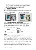
Page 20: ...nunciators is customizable See section 12 1 LCD visual alarm and status codes for details Figure 1 3 Liquid Crystal Display and annunciators 1 3 3 Integral multivariable XIMV assembly The External Integral Multi Variable XIMV contains circuitry for processing all analog measurements and provides the primary measurement capability for the XFCG5 flow computer The unit is designed to provide EMI RFI ...

Page 21: ...5 device with host systems or external devices Some factory pre configured ports support typical communication scenarios and are enabled at the factory Other options must be enabled and configured during initial startup and configuration Several communication protocols are available and supported by the ports 1 3 5 1 Local communication Ports configured for local communication direct connection su...

Page 22: ...h Bluetooth clients operator access Onboard Bluetooth connections require an antenna Bluetooth USB dongle Use USB port Bluetooth to USB dongle connects to USB port Local communication with Bluetooth clients operator access Bluetooth to USB dongles adapter have the antenna integrated No additional antenna needed 1 3 5 2 Remote serial communication Ports configured for remote serial communication co...

Page 23: ...guration and commissioning setup Operation and performance monitoring Adding configuring and optimizing applications configuration customization Calibration Data collection Device configuration backup Device software updates Application licensing Report view and generation Troubleshooting PCCU32 supports local or remote connections with the XSeriesG5 device over serial RS 232 USB Ethernet or wirel...

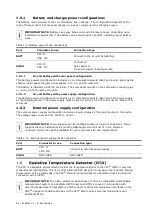
Page 24: ...arging source The power supply must be set to 14 5 to 15 5 Vdc and must be rated for 2A minimum 1 5 2 External power supply configuration The external power supply configuration includes a power supply as the power source to the device The voltage range must be from 12Vdc to 14Vdc IMPORTANT NOTE Power supplies can be installed outside or inside of enclosures Power supplies that are installed insid...

Page 25: ...2106026MNAA XSERIESG5 25 ...

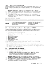
Page 26: ...efer to the Data Sheets Plan the power equipment installation based on the requirements for the power source selected ABB approved battery charger systems and external power supplies are available See section 1 5 Power supply equipment for details Space and materials should be available for power equipment installed outside of the enclosure Determine the device installation location Review the opt...

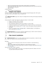
Page 27: ... used to connect to the device in the field We recommend you obtain the software prior to field installation in case you are unable to access online ABB resources from the field IMPORTANT NOTE If you are unable to locate or download the PCCU software or need assistance during its installation on your laptop call ABB technical support See Contact us To download or review release notes for the lates...

Page 28: ... One 1 2 inch x 40 inch pipe length may be extended if mounting a solar panel EFM plus bolts and washers 5 valve manifold 2 stabilizers futbols plus bolts and washers Wall mount installation One 1 enclosure mounting kit includes instructions brackets U bolts and fastening hardware Four 4 wall fasteners length and girth determined by technician based on wall thickness and materials EFM plus bolts a...

Page 29: ...e materials received Check for missing or incorrect parts Inspect each item for damage XFCG5 or XRCG5 exterior LCD display optional equipment if purchased If there are missing incorrect damaged parts or noticeable defects call the ABB main office number listed in Contact us IMPORTANT NOTE Do not return equipment to ABB without prior written consent Returns are subject to the terms and conditions s...

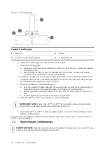
Page 30: ...re to the mounting pipe a Hold the enclosure in place against the mounting pipe and insert a U bolt around the pipe and through the corresponding holes on the upper mounting bracket c Add the flat washer and split washer onto the U bolt then screw the nut onto the U bolt d Repeat steps 6a and 6b for the second mounting bracket Raise the XFCG5 or XRCG5 into position on the mounting pipe IMPORTANT N...

Page 31: ...t instructions supplied with the mounting kit Determine the appropriate mounting height for the XFCG5 or XRCG5 to allow some downward slope from the XIMV and manifold to the meter run tap valves This allows condensate to drain back into the pipe Drill the upper mounting holes in the wall support Measure the distance between the top and bottom mounting bracket holes Locate and drill the lower mount...

Page 32: ...the nut onto the ferrule and tighten Repeat step 5 for each tubing connection point Leak test the manifold and tap valve connections See section 3 9 Leak test manifold and tubing connections Figure 3 2 XFCG5 with XIMV attached to a 5 valve manifold Legend XFCG5 with XIMV attached to a 5 valve manifold 1 Instrument manifold 5 valve 2 XIMV 3 7 1 Overview The XRCG5 6990 is intended for rack mounting ...

Page 33: ...ll be applicable to the XRCG5 6990 but wired to the corresponding plug on the rear of the enclosure Table 10 shows XRCG5 jumper termination panel correlation Table 3 1 XRCG5 Main electronic board to termination panel correlation chart XRCG5 main electronic board XRCG5 6990 termination panel J6 COMM1 P6A J6 COMM2 P6B J8 Digital I O A P8A J8 Digital I O B P8B J20 AuxPwr Output P20 J23 Analog Inputs ...

Page 34: ...d tubing connections must be leak tested before power application Connection leaks between the tap valves the orifice the manifold and the XIMV can introduce measurement and calibration errors Materials Liquid leak detector Pressure calibration device DANGER Serious damage to health risk to life Manifold and tubing connection leaks could create a build up of explosive gases Do not apply power befo...

Page 35: ...ng connections Connection points between the flange and the manifold IMPORTANT NOTE Bubbles in the liquid indicate a loose or poor connection Use a wrench to tighten connections and recheck NOTICE Equipment damage Do not over tighten the connections After verification that all connections are leak free proceed to install the RTD An optional 100 Ω platinum RTD 000385 Alpha measures real time flowin...

Page 36: ...d by technician Nylon tie wraps Install the RTD probe Insert the RTD probe into the thermowell to determine the depth setting for the probe spring Figure 3 6 Typical RTD installation Use snap ring pliers to adjust the retaining ring below the spring on the probe Probe depth should be set so it is spring loaded against the bottom of the thermowell Figure 3 7 RTD probe connector Legend RTD Probe Con...

Page 37: ... the gland so that the cable turns down immediately This will keep moisture from seeping into the housing along the RTD cable WARNING Bodily injury Wire peripheral devices to the flow computer electronic board before power is applied If the flow computer has been powered up disconnect power before performing field wiring Wire the RTD Open the flow computer enclosure door Using a small slotted scre...

Page 38: ...ormation Install the antenna to support onboard Bluetooth and Wi Fi wireless interfaces Use onboard connector ANT 1 J42 to connect the antenna Use the cap to isolate the unused antenna connector ANT 2 Place communication equipment such as a radio in the communication compartment inside of the enclosure For radios with serial interfaces use the available onboard COMM port COMM1 port is preconfigure...

Page 39: ...cate the battery shelf Place the battery on the compartment shelf do not allow the battery terminals to contact any metal surface inside the enclosure DANGER Bodily injury Do not allow the battery terminals to contact any metal surface When the positive and negative battery terminals contact a conductive material it creates a short circuit and could result in sparks property damage and possible ex...

Page 40: ...allation Check the solar panel using a digital voltmeter to verify polarity and output voltage before installation If the measured output voltage is within the manufacturer s specification as defined by the specification sheet supplied with the panel continue with the installation If the measured voltage is out of specification contact ABB for a replacement panel Install the mounting bracket on th...

Page 41: ... locate the CHRG terminal block J5 on the XFCG5 J17 on the XRCG5 Remove the cable nut from the cable conduit elbow and insert the cable and conduit ends through the access hole in the enclosure Pull the cable into the enclosure leaving enough cable to reach the CHRG terminal block J5 on the XFCG5 J17 on the XRCG5 Replace the cable nut on the cord and conduit end inside of the enclosure and screw t...

Page 42: ...E Equipment damage or loss of data Do not over tighten the terminal connector screws as this may damage the wires NOTICE Equipment damage or loss of data Do not connect the solar panel to the electronic board before battery connection Damage to the board will void any warranty ...

Page 43: ...MM 1 and COMM 2 connect XSeriesG5 to devices with serial interfaces RS 232 or RS 485 For example Communication equipment Serial Radio systems Modems legacy External measurement equipment Single or multivariable measurement transmitters The following table provides the ports general description Table 5 1 Serial COMM port description Board ID Port Connector type Data transfer rate port speed Use con...

Page 44: ... or pinout tables IMPORTANT NOTE Use pins on both terminal blocks to wire COMM1 or COMM2 on the XFCG5 Remove both terminal block connectors from the board to wire based on communication type For RS 232 refer to Figures below COMM1 COMM2 and Table 5 3 For RS 485 refer to Figure 5 3 COMM1 Figure 5 4 COMM2 and Table 5 4 Figure 5 1 XFCG5 R 232 COMM1 IMPORTANT NOTE Typically only TXD RXD and GND may be...

Page 45: ... Sw VBATT Sw VBATT 4 TXD 5 6 RXD 7 8 RTS 9 CTS 10 DTR 11 DCD 12 TXD 13 RXD 14 RTS 15 CTS 16 OPERATE OPERATE Blank cells carry no signal IMPORTANT NOTE Figure 5 3 COMM1 and Figure 5 4 COMM2 show connection lines to a single device RS 485 supports multiple devices per port For additional wiring options search additional user drawings at www abb com upstream ...

Page 46: ...municate with a third party RS 485 device The figure above illustrates all lines associated with the COMM1 or COMM2 RS 485 module Figure 5 4 XFCG5 R 485 COMM2 Table 5 4 XFCG5 RS 485 COMM1 and COMM 2 PIN RS 485 COMM1 RS 485 COMM2 1 GND GND 2 VBATT VBATT 3 Sw VBATT Sw VBATT 4 BUS 5 BUS 6 BUS 7 BUS 8 RRTS 12 BUS 13 BUS 14 RRTS ...

Page 47: ...to wire COMM1 or J6 B to wire COMM2 See Figure 5 5 RS 232 or Figure 5 6 RS 485 Refer to Table 5 4 for complete pinout for both ports IMPORTANT NOTE Wiring for RS 485 communication set the termination jumpers J7 or J10 in the correc Figure 5 5 XRC RS 232 COMM 1 IMPORTANT NOTE Typically only TXD RXD and GND may be required to communicate with a third party RS 232 device The figure above illustrates ...

Page 48: ...NAA Figure 5 6 XRC RS 485 COMM 1 Table 5 5 XRC COMM 1 and COMM 2 pinouts PIN RS 232 COMM 1 and 2 RS 485 COMM 1 and 2 1 VBATT VBATT 2 GND GND 3 SW VBATT SW VBATT 4 OPER OPER 5 RTS RRTS 6 DCD BUS 7 RXD BUS 8 CTS BUS 9 TXD BUS ...

Page 49: ...ith this voltage range Connecting an incompatible device may result in damage to the device Inputs provide the ability to read and monitor signals transmitted from external devices Outputs provide the ability to send signals to control external devices The following table provides the I O general description For detailed specifications visit www abb com upstream to review product datasheets IMPORT...

Page 50: ...rt the monitoring of external devices Both DIs and PIs are supported on the same terminals Digital inputs can read an external contact This is primarily used as a status input to read external equipment This contact must be closed to be considered on The on condition is recorded in the log period alarms and can trigger the action of the flow computer s digital voltage 12 Vdc output is off is defin...

Page 51: ...the pinout table for wiring IMPORTANT NOTE The XFCG5 AIs support voltage inputs by default To support current 4 20 mA inputs add a 250 ohm resistor across the and terminals See section 6 1 1 Analog inputs AI for additional information on input mode and range Figure 6 1 XFCG5 AI terminals Table 6 4 XFCG5 AI Pinouts Input Pin Description AI 1 1 Input signal Input ground 2 AI 2 3 Input signal Input g...

Page 52: ... onboard digital inputs Figure 6 3 shows the Digital I O terminals on the XFCG5 and the input mode switches The input mode switches support standard pulse inputs STD or pulse inputs from Coriolis IEC Remember to set the switch to the correct position based on the type of pulse input signal expected Use S3 for DI PI 1 or S4 for DI PI 2 Listed below are the DIs and DOs for the XFCG5 Figure 6 3 XFCG5...

Page 53: ... IEC Remember to set the switch to the correct position based on the pulse input signal expected Use S3 for DI PI 1 S4 for DI PI 2 S7 for DI PI 3 and S8 for DI PI 4 By default the debounce jumpers are set to enable debounce on the DI PI Listed below are the DIs and DOs for the XRCG5 Figure 6 4 XRC DI PI DO terminals input mode switches and debounce jumpers Table 6 7 XRC DI PI DO Pinouts I O Pin J8...

Page 54: ... the supply voltage from falling to zero for a short period of time 2 5 seconds This delay allows the system time to save all persistent data such as trending and restart configuration The XFCG5 and XRCG5 power on sequence is initiated as soon as power is connected The LCD displays the following information as the controller completes the startup Figure 7 1 XFCG5 Display startup messages part numb...

Page 55: ...Super capacitor charging at boot time If LCD does not display the power on sequence try adjusting the contrast Refer to section 10 6 Adjust the LCD contrast If the power on sequence fails to initiate or complete press the reset button shown below Figure 7 3 Reset button and coldboot button 7 3 2 Connect the charger To connect the charger select the procedure applicable to the type of charger used ...

Page 56: ...4Vdc NOTICE Equipment damage A battery cannot be used when the XFCG5 or XRCG5 is in external power mode To connect the external power supply Review the manufacturer s instruction supplied with the external power supply Connect the external power supply cable to the BATT connector as shown below Observe the polarity and IMPORTANT NOTE Connections to the BATT connector require a special cable adapte...

Page 57: ...he last time Totalflow was running or when the power was lost This is the time most often used OS Build Time In case the Last Totalflow Running Time could not be retrieved the build time of the OS will be used as the last known good time If system time is lost the system and event logs will display the following messages System Log System time was lost so restoring the last known time Event Log in...

Page 58: ...e for all connections XSeriesG5 Ethernet ports autosense cable type IMPORTANT NOTE PCCU32 version 7 65 software or newer is required to communicate with the XFCG5 or XRCG5 for configuration Previous versions of PCCU32 are not compatible It is assumed that PCCU32 is already installed in the PC or laptop used to connect to the XFCG5 or XRCG5 If not see section 2 5 Download PCCU IMPORTANT NOTE PCCU32...

Page 59: ...CCU32 tool bar click Entry to connect to the device Figure 8 2 PCCU32 Tool bar and Entry Legend PCCU 32 Elements Number Element name 1 Tool bar 2 Entry button If the XFCG5 or XRCG5 clock date and time are different from the laptop s a message box displays with the option to synchronize the date and time ...

Page 60: ...es to synchronize date and time now When successfully connected to the XFCG5 or XRCG5 the screen displays the device and measurement variables Figure 8 4 PCCU32 XFCG5 Entry screen Use PCCU Expert view to complete initial and advanced configuration Change the view while connected to the XFCG5 or XRCG5 While connected to the XFCG5 or XRCG5 Entry mode on the top PCCU32 menu bar select View Select Exp...

Page 61: ...6 Station Setup Set up the basic station configuration parameters identified in the following table Table 8 2 Required station setup Entry Format Description Station ID 10 digits alphanumeric The station identifier code is unique If running a multiple tube station the station ID is the same for all tubes on the device If left blank on a single tube device the station ID will be the same as the dev...

Page 62: ...n Setup tab scroll down to the LCD Display Date Time Format See the figure below Figure 8 7 Station Setup detail Select the preferred Date Time Format mmddyy or yymmdd Select the preferred Date Separator slash dash or period Select the preferred Time Separator colon or period Click Send to save the station settings The XFCG5 or XRCG5 shipped with standard configuration and the gas orifice measurem...

Page 63: ...f live readings set the Use Fixed Temperature field to Yes c In the Fixed Temperature field type the value for the fixed temperature On the navigation tree click Flow Measurement Setup On the General tab verify and change if necessary the required parameters a In the Calculation Type field select the calculation standard for this tube b In the Fpv Method field select the compressibility method for...

Page 64: ... are the minimum requirements to get a Totalflow XFCG5 or XRCG5 online and measuring gas There are many more steps depending on the site and company requirements Configure and enable communication interfaces when needed Before configuration wire communication or peripheral equipment to the serial communication COMM terminals See section 5 Wire COMM ports For remote or local network communication n...

Page 65: ...l interface required See section 5 Wire COMM ports In the PCCU navigation tree click Communications On the Communication Setup tab select COM1 TF Remote COM 1 Figure 8 12 TF Remote COM 1 On the Protocol menu select the appropriate protocol if not using the default Totalflow Remote Under Serial Port Settings on the Interface menu select the communication interface RS 232 RS 485 or RS 232 Modem Veri...

Page 66: ...active and listening for communication See the following figure Figure 8 13 Verify the communications set up for COMM1 IMPORTANT NOTE The symbol flashes according to the listen cycle defined for the communication port The default listen cycle is 4 If set to zero the symbol should be displayed continuously See the PCCU32 Help files for communication port setup to learn how this setting effects powe...

Page 67: ...e the communication equipment according to the type of serial interface required see section 5 Wire COMM ports On the PCCU navigation tree click Communications Figure 8 14 Spare COM 2 On the Communication Setup screen select COM2 Spare COM2 In the Port description field type a description for the port Ensure that the port description uniquely identifies the port From the Protocol menu select the p...

Page 68: ...at the name is unique The Network ID is the name broadcast on the wireless networks and must be detected by wireless devices prior to establishing connection Configure the network ID On the PCCU Entry mode navigation tree select Communications Select the Network tab To change the default in the Network ID field type the desired name not recommended Click Send to save Use the Network ID to identify...

Page 69: ...able to connect to the DHCP server contact the IT administrator Ping the IP address of the device from the corporate network or local switch and verify that the device replies IMPORTANT NOTE To restart or reinitialize the Ethernet interface click the Restart button on the Ethernet screen It is no longer necessary to restart the device 8 7 5 Enable Wi Fi The XFCG5 and XRCG5 support Wi Fi Access Poi...

Page 70: ...ting Wi Fi to factory defaults resets all Wi Fi parameters not only the passcode Click Send to save the new passcode Click Yes to confirm A message displays indicating that the passcode change is successful Take note of the IP address default 192 168 1 1 as it is required to establish connection using PCCU IMPORTANT NOTE The default IP address assigned to the XFCG5 and XRCG5 for Wi Fi connections ...

Page 71: ... for the Wi Fi network default 192 168 1 1 Click Close to exit PCCU setup and return to the main PCCU screen On the PCCU toolbar click Entry and verify connection is established 8 7 6 Enable Bluetooth The XFCG5 and XRCG5 support Bluetooth functionality to allow wireless local access This procedure enables onboard Bluetooth For additional details or if using a USB dongle click Help from the Bluetoo...

Page 72: ... 8 19 Enable Bluetooth Select the Communication Setup tab The Bluetooth interface is unused in the port list Figure 8 20 Communication Setup for Bluetooth Select Bluetooth Unused Select Add New Device Application See the figure below ...

Page 73: ...h See the figure below Figure 8 22 Verify Bluetooth application assignment Start a new instance of PCCU to test the Bluetooth connection or close the current connection Start PCCU from the top menu and select Setup Under Communications PCCU Connect method select Bluetooth Select Search for Bluetooth devices Verify that the XFCG5 or XRCG5 Network ID displays in the list of detected devices Select t...

Page 74: ...ate the device measurement The XFCG5 and XRCG5 are calibrated at the factory before shipping However shipping and installation may introduce errors into the measurement results To verify measurement accuracy perform pressure checks IMPORTANT NOTE Save the device s data and configuration before and after calibration procedures For details on calibration or device data backup see section 11 Calibrat...

Page 75: ... side equalizer valve 6 XIMV Verify the equalization valves items 1 and 3 are open Verify the manifold vent valve is closed Slowly open the stream tap valves to open the process stream creating flow Wait until the system has pressurized typically less than 1 minute before continuing Close the equalization valves items 1 and 3 on the manifold 8 8 3 Optional volume reset recommended This procedure a...

Page 76: ...connections communication ports default names Default state Default protocol Security feature available MMI port name MMI Serial COM0 Enabled Totalflow Local Read only Bi Level Security code authentication or Role base Authentication RBAC USB port name Totalflow USB Enabled Totalflow Local Read only Bi Level Security code authentication or Role base Authentication RBAC Ethernet port name Totalflow...

Page 77: ...CP ports on an XSeriesG5 Default TCP port User configurable Protocol using the port Description 9999 Yes Totalflow TCP Assigned to connections used for device monitoring configuration and data collection or polling PCCU WinCCU TDS and third party SCADA systems request these connections 65535 No Device Loader TCP Assigned to the device loader connections for device software update PCCU requests thi...

Page 78: ...ides the DOS threshold rates per packet type at which the device stops responding Table 9 5 Denial of Service DOS threshold rates Packet type Description Ethernet 5 Mbps 7440 packets sec ARP 2 Mbps 2976 packets sec IP 3 Mbps 4464 packets sec ICMP 4 Mbps 5952 packets sec UDP 3 Mbps 4464 packets sec TCP 1 Mbps 1488 packets sec The following table describes recommended guidelines to secure access to ...

Page 79: ...d Secure Bluetooth access Enable Bluetooth only when required Enable RBAC authentication on the port See 9 6 5 Enable RBAC authentication on communication ports Secure SSH SFTP access Enable the SSH SFTP service only when required The default SSH SFTP private keys should be changed for all accounts The SSH SFTP private keys should always be passphrase protected See section 9 7 Secure the SSH SFTP ...

Page 80: ...Switch Status field shows Off Figure 9 3 Station Setup tab Security switch status Type a four digit security code for Security Code Level 1 read only access Type a four digit security code for Security Code Level 2 read and write access IMPORTANT NOTE Record the security codes Once saved they are not visible on the Station Setup tab Click Send On the board set the XFCG5 or XRCG5 security switch to...

Page 81: ...nctionality is accessed the Send button is also grayed out NOTICE Security override After RBAC is implemented it overrides the device enforced bi level security and PCCU32 enforced security When RBAC is enforced it replaces all other security and is specifically implemented on a port by port basis 9 6 1 Default access roles Default roles are automatically available in PCCU32 Administrator Expert A...

Page 82: ...ion on communication ports Return here when complete Type a description of the security file in the Description field Save the new security control file Click Save As Type a password for the security file and click OK Click Save to keep the default file name or change the name and click Save IMPORTANT NOTE At the top right corner of the Security Editor screen is the Security Key Before the securit...

Page 83: ...security system Click Add User on the RBAC Security Editor screen Type the user name in the Name field of the User Name and Password dialog box Figure 9 5 User Name and Password dialog box Type the user password in the Password field Click OK The new user account will appear in the list of users Click Role beside the new user account and assign the appropriate role IMPORTANT NOTE During the initia...

Page 84: ...ting Functionality Disabled Does not perform any RBAC security functions on the port Enabled Enables full security over the port to RBAC If the administrator name and or password are lost or forgotten it will be necessary to reset to the factory default configuration Note that all data and the running configuration will be deleted Enable by Security Switch Enables security over the port to RBAC bu...

Page 85: ... or Expert view to configure or override communication port security In PCCU32 Entry mode click the communication port to secure Set the Authentication value to Enabled or Enable by Security Switch in the Setup tab Figure 9 8 Click Send Repeat steps 1 3 for each of the communication ports Figure 9 8 Enabling communication port authentication Entry mode 9 6 6 Use default RBAC credentials Each time ...

Page 86: ...credentials in PCCU Click the Setup icon on the main toolbar or click Operate Setup System Setup Set the following under Auto Connect Figure 9 10 Set the default connection mode Entry Collect etc Click Help for additional details Select Use Default Role Based Access Control credentials Type in the Default Role Based Access Control Username Type in the Default Role Based Access Control Password Fig...

Page 87: ...h read only SFTP connections see the SSH and SFTP service overview topic in PCCU online help Table 9 8 Security keys Account Name Access privileges Default keys Access Totalflow user Only SFTP access Read only Totalflow user private key The following folders and their contents are available for download Crash Dumps Flash Main Totalflow application App Factory configuration Startup cold configurati...

Page 88: ...upstream The private keys for developer or tech support accounts along with their respective passphrases for SFTP If changing the keys for the first time request the default keys from ABB If the keys have been previously updated use those keys instead IMPORTANT NOTE There are other options for the third party software Puttygen and Filezilla are used as examples to illustrate the update procedure I...

Page 89: ...2106026MNAA XSERIESG5 89 Figure 9 11 Puttygen Key Generator Move the mouse to the Key blank field under the progress bar see highlighted area below Figure 9 12 Puttygen Key Generator Key blank field ...

Page 90: ...s the new public key Figure 9 13 New public key In the Key comment field leave default includes the date of key generation or another preferred description In the Key passphrase and Confirm passphrase fields create a strong private passphrase a passphrase protects the use of the private key It is recommended for additional security ...

Page 91: ...nd passphrase Click Save private key Figure 9 15 Save private key and passphrase Type the file name and select the desired location to store the key file at file browser window The private key file has the ppk extension This new private key along with its ...

Page 92: ...ation to save private key file Click Save The file browser closes Right click on the Key field where the public key displays Click Select All IMPORTANT NOTE Do not click Save public key for this process Figure 9 17 Select public key content from Puttygen key generator key field After the public key is selected right click on the highlighted text and click Copy ...

Page 93: ...he developer and tech support accounts can be accessed either by the newly created private key or the previous set of private keys for developer and tech support accounts R_rootkey txt A key with this name replaces R all the available developer and tech support public keys in the device After the key update operation the developer and tech support accounts can only be accessed by the newly created...

Page 94: ...on to access the device over a network If using a local point to point to connection configure accordingly Click Help for additional details Figure 9 20 Enable and configure Ethernet Network Adapter Click Send to save any changes Connect the XSeriesG5 device to the network or to the laptop or PC if the Ethernet connection is local Keep your serial or USB connection open Launch the FileZilla applic...

Page 95: ...rst time use the default developer or tech support private key provided by ABB If the keys were previously updated then use those keys instead Click Connect Figure 9 21 FileZilla Site Manager connection setup If the private key is passphrase protected a window requesting the passphrase displays before granting the connection Figure 9 22 Type the passphrase in the Password field For a default key u...

Page 96: ...w displays the file directories of the laptop or PC on the left and the device on the right Figure 9 23 FileZilla New Site window Navigate to and open the directory containing the newly created public key text file on the left Navigate to and open the Flash AppData ssh directory on the Totalflow device on the right The device updates the keys only if it finds them in them in the specified director...

Page 97: ...public key file and select Upload from the drop down menu Figure 9 25 Upload public key from laptop to device Verify that the file is copied to the Flash AppData ssh directory The name of the file should display under that directory when the upload is complete Figure 9 26 Verify public key upload is complete ...

Page 98: ...tion with new private public key pair Verify that the public key update is successful by establishing a new SFTP connection from FileZilla using the newly created key and passphrase to authenticate To verify Restart FileZilla Click Open the Site Manager The Site Manager window displays Configure the General tab parameters as follows Host Type the device s IP address Port Type 9696 Protocol Select ...

Page 99: ...2106026MNAA XSERIESG5 99 IMPORTANT NOTE Keep private key files stored in a safe location accessible only to authorized personnel and security managers ...

Page 100: ...iguration file could result in a loss of measurement data and require a complete system reconfiguration NOTICE Equipment damage The external power charger and battery connections must be removed before removing all other cables boards and field connections Connecting or disconnecting cables and wires on the electronic board while power is applied can damage the electronic components Do not reconne...

Page 101: ... laptop or PC You can use backup configuration files to restore service in the event of equipment failure part replacement or to replicate the configuration in other devices IMPORTANT NOTE tfData and tfCold warm and cold are terms used to refer to the running and startup configuration respectively 10 1 2 1 Update the startup cold configuration This procedure saves the running warm configuration to...

Page 102: ...guration to a laptop or PC This procedure saves the startup cold configuration to a laptop or PC using the 32 Bit Loader This requires a separate connection established from the loader not from entry mode IMPORTANT NOTE Click Help on the 32 Bit Loader screens for additional details To save the startup configuration If still connected with the device on entry mode close that connection to return to...

Page 103: ...nection setup window displays Figure 10 4 Connection Setup Type the connection setup parameters and click Connect When the connection is successful the main loader screen displays Click Services Save from the menu bar on the main Loader screen The Save Software from Device window displays ...

Page 104: ...dow To save only the configuration clear all options except Config Figure 10 6 Config checkbox Click Start A browser window displays Locate the destination folder for the configuration type the file name and click Save Take note of the location of the configuration file ...

Page 105: ...ied in the selected directory Figure 10 8 Loader status logs Click Close to exit the Save window Click Close to exit the 32 Bit Loader When a measurement application is running a clock change could affect the times when log period entries are made To protect the integrity of the accounting audit trail the flow computer handles these types of clock changes as follows ...

Page 106: ...he balance of the hourly data Example If the present time is 5 05 p m and the clock is changed to 4 55 p m of the same day the log period entry reflects only a five minute average accumulation When the next log record is written the period is based on a 60 minute accumulation CAUTION Equipment Property damage Follow the procedures in section 10 5 Remove and restore power when instructed to do so i...

Page 107: ...ore restart follow procedures in section 10 1 Preserve data and configuration 10 4 6 Cold restart with onboard COLDBOOT button 10 4 7 Cold restart from the device loader 10 4 8 Cold restart from terminal mode Factory restart The device Shuts down all applications Deletes the running configuration and repopulates it using the factory configuration Restarts with factory defaults Manual trigger When ...

Page 108: ...bserve the display The LCD shows that the unit is shutting down and restarting IMPORTANT NOTE If the device does not restart press and hold the RESET button for eight seconds 10 4 3 Warm restart from the device loader This procedure performs the warm restart from the 32 bit loader The procedure can be performed while on a local or remote Loader connection The procedure causes the device to restart...

Page 109: ...re can be performed while on a local or remote PCCU connection IMPORTANT NOTE This procedure requires Expert view To restart the controller using System Shutdown then Reset Connect the PC running PCCU32 to the flow computer Launch PCCU32 and click Entry Click View on the PCCU32 menu and select Expert from the drop down list Click the top item on the navigation tree The Station Setup tab displays S...

Page 110: ...d restart with onboard COLDBOOT button This procedure uses the COLDBOOT and RESET buttons on the electronic board to restart a device It causes the device to restart using the startup cold configuration You must have physical access to the device and be able to open the enclosure door and access the electronic board NOTICE Loss of data Perform the procedures in section 10 1 Preserve data and confi...

Page 111: ... or remote Loader connection but it is highly recommended that the cold restart is performed locally The cold restart causes the device to restart using the startup cold configuration NOTICE Loss of data Perform the procedures in 10 1 Preserve data and configuration before a cold start This avoids loss of the data and the need for a complete system reconfiguration If the startup cold configuration...

Page 112: ...d restart requires you to type a command NOTICE Loss of data Perform the procedures in section 10 1 Preserve data and configuration before a cold start This avoids loss of the data and the need for a complete system reconfiguration If the startup cold configuration does not have the latest network connection configuration the restart causes loss of network connectivity Updating the startup configu...

Page 113: ...pment damage or loss of data A restart with factory defaults deletes all data and previous configurations both current startup and running configurations are lost Perform the procedures in section 10 1 Preserve data and configuration before restoring factory defaults Network communication parameters will be overwritten with factory defaults as well If this restart is triggered remotely on a networ...

Page 114: ... NOTE Do not remove power if the device does not have the lithium battery enabled or in place If the lithium battery is not enabled has failed or was removed the clock resets to factory defaults See section 10 7 2 Replace the lithium battery IMPORTANT NOTE This procedure requires physical access to the device to open the enclosure door for access to the electronic board 10 5 1 Remove power from th...

Page 115: ...ct the battery to the BATT connector J1 on the XFCG5 or J16 on the XRCG5 b Connect the charging source connector to the CHRG terminal J5 on the XFCG5 or J17 on the XRCG5 If externally powered connect the outside power source to the BATT connector J1 on the XFCG5 or J16 on the XRCG5 The LCD contrast is controlled by the onboard potentiometer R139 To adjust the contrast Locate the small onboard pote...

Page 116: ...ter which will assist with disassembly and reassembly Figure 10 22 Exploded view of an XSeriesG5 enclosure Table 10 2 Exploded view Legend Number Part name Number Part Name Number Part Name 1 Enclosure 4 Battery tray 7 Lithium battery 2 MMI connector 5 Door latch 8 Electronic board to transducer cable 3 Door 6 LCD 9 Transducer housing 10 7 1 Replace the 12 Vdc battery These instructions describe t...

Page 117: ...he battery and battery cable from the battery compartment Put the new battery in place Ensure that the battery terminals do not touch the metal surfaces inside of the enclosure Connect battery cable to the new battery terminals observing polarity Reconnect battery and charger following the steps for battery mode in section 10 5 2 Reconnect power to the electronic board Verify on the LCD that the c...

Page 118: ... of the connecting laptop or PC figure below Before you change the factory default determine if your company s policies specify when during the new board setup the date time should be updated Click Help at the prompt for more details Figure 10 23 Change time date factory defaults on a new board 10 7 4 Replace the LCD assembly In some XSeriesG5 models the LCD assembly is installed behind of the ele...

Page 119: ...steps below for those models Remove the electronic board being careful not to drop the mounting screws and washers a Remove the mounting screw holding the ground wire at the bottom right corner of the board Then remove the hex standoff that held the screw b Remove the three remaining screws from the three remaining corners and remove the board c Place the board on a safe clean non metal surface Re...

Page 120: ...odules Connect with the device using PCCU entry mode Follow the procedures to backup device data and configuration as described in section 10 1 Preserve data and configuration Verify that the lithium battery backup is enabled and that the lithium battery voltage level is OK a View the scrolling parameters on the LCD Verify that the Lithium Backup parameter displays Yes If it displays No enable the...

Page 121: ...ith a module of a different type make sure to rewire the terminal connector to the match the type 10 7 5 4 Restore power to the board After module insertion is complete Restore power to the board as described in section 10 5 2 Reconnect power to the electronic board Verify startup sequence is completed Close the enclosure door Verify COMM connections If new equipment has been added Review the wiri...

Page 122: ...rchived WinCCU recalculates the flow volume based on the previous and current markers This allows more accurate results of the flow volume 11 1 1 Static pressure checks The flow computer supports SP calibration pressure checks and logs the pressure marker check points Perform this check prior to and directly following the calibration During normal operation of the flow computer the display provide...

Page 123: ... both the high and low equalizer valves Close both the downstream and upstream tap valves Open the atmospheric vent valve Enter a pressure marker for atmospheric pressure PSIA Enter zero if in Gauge mode or the barometric pressure or contract value if in Absolute mode Click OK Close the atmospheric vent valve Click Enter Pressure Check Value Connect the calibration standard to the calibration test...

Page 124: ...ll will be pressurized by closing both the high and low side orifice valves opening the vent to atmosphere closing the atmosphere vent and then opening both the high and low bypass valves The resulting comparison pressure must not be greater than the maximum pressure rating of the static pressure cell Select Calibration on the tool bar to place the flow computer in hold mode Select the measurement...

Page 125: ...te mode other points of calibration are determined by adding the PSI reading and the barometric pressure to arrive at the PSIA Enter this reading Operating in PCCU32 Gauge mode the readings may be entered as read Upon completion a barometric pressure reading is entered 11 1 3 2 Calculating PSI To convert barometric pressure measured in inches of mercury to PSI perform the following calculation Bar...

Page 126: ...indow Example If the transducer has a URL of 1500 then 50 of that pressure or the Target pressure is 750 In a 5 Point calibration this will be the third value and will be equal to 75 of the transducers URL Example If the transducer has a URL of 1500 then 75 of that pressure or the Target pressure is 1125 When the current reading stabilizes click OK otherwise enter a different value pressure value ...

Page 127: ...he low side is vented to atmosphere Apply pressure to 100 of the transducer range URL or 100 of the target value When the current reading stabilizes click OK otherwise enter a different value pressure value from the calibration source and then click OK After the previous value is accepted the next calibration point button will activate Click the activated button Apply pressure to the next target v...

Page 128: ...lick Zero Transducer Check Continuous Update When the current reading stabilizes enter a zero for Gauge mode or enter the barometric pressure for Absolute mode and click OK 11 2 2 Differential pressure The DP can be zeroed without recalibrating If the DP indicates a linear shift enter a new zero 0 This shifts the DP curve After the hold state initiates select Zero Transducer Select Calibration on ...

Page 129: ...qual to 100 of the transducer temperature range for the high calibration point When the current reading stabilizes click OK otherwise enter a different value temperature value from the calibration source and then click OK After the previous value is accepted the next calibration point button will activate Click the activated button Apply the resistance equal to the next target value as shown in th...

Page 130: ...e and bias value to be used IMPORTANT NOTE The current temperature value Tf will increase or decrease to reflect the effect of the bias The bias value will not affect the Fixed Temperature which is specified on the Setup tab Click Close to exit Calibration and exit Hold mode Click OK The calibration for analog input AI can be a 3 point or 5 point calibration Table 11 3 Table 11 3 AI calibration po...

Page 131: ...alibration Only use wires of the correct length from the XSeriesG5 to the external device when you connect the calibrator Or place the calibrator at the location where the external device is installed To prepare and connect the calibration equipment Power off the XSeriesG5 Disconnect the wires from the external device Set the calibrator to the same signal type voltage or current as the AI mode set...

Page 132: ...If calibrating on the XFC Insert a precision resistor across the selected AI pins If calibrating on the XRC Place the mode selector jumper J21 J22 J24 J25 or J26 across pins 1 and 2 for the selected AI 11 5 3 Analog input calibration voltage mode This procedure describes a three 3 point calibration Available target values for this option display in the calibration window and become active in calib...

Page 133: ... is the default displayed Figure 11 6 AI voltage default calibration values Select either the 3 Point or 5 Point calibration from the Calibration drop down list Verify that only the Zero Input and Low Cal Point buttons are enabled and highlighted The system enables the buttons in the order required for the calibration Click the Range field The Analog Input Range dialog box displays Type the extern...

Page 134: ...lue is 50 000 for the range value of 100 Adjust the calibrator to apply the 50 value of the external device signal range For example if the signal range of the external device is 1 5 Vdc apply 3 Vdc Observe the value in the Current Reading field When the value stabilizes click OK When the Calibration Complete message displays click OK Verify that the Entry values are updated and that the Current V...

Page 135: ...er to the XSeriesG5 Verify that the calibrator is set to the current signal type Turn on the calibrator to supply the signal Click the Calibrate icon on the PCCU toolbar the Calibrate icon shows tools The Analog Input 1 tab displays Click another AI tab if necessary to calibrate In this example AI 2 displays Analog Input 2 tab Figure 11 9 AI current default calibration values Click Calibration and...

Page 136: ...with the target mid value automatically calculated For example the value display is 50 000 for the range value of 100 Adjust the calibrator to apply the mid range value 50 of the signal range For example if the signal range of the external device is 4 to 20 mA apply 12 mA Observe the value in the Current Reading field When the value stabilizes click OK When the Calibration Complete message display...

Page 137: ...rs proceed to section 11 5 6 Repeat calibration in case of errors 11 5 6 Repeat calibration in case of errors If the displayed input values are not valid or do not stabilize the calibration might not be correct In Entry mode the calibrated AI indicates it has been Field calibrated regardless of whether the calibration was successful or not This procedure sets the AI calibration status back to Fact...

Page 138: ... XRCG5 AIs and mode selector jumpers default setting To set the AI to voltage mode If calibrating on the XFC AIs support voltage mode by default Ensure that there are no external resistors connected across the AI pins If calibrating on the XRC Verify that the mode selector jumper J21 J22 J24 J25 or J26 is across pins 2 and 3 for the selected AI To set the AI to current mode If calibrating on the X...

Page 139: ...sponse Receiving Data Processing request Nak Negative acknowledgement with packet list Ack Positive acknowledgement of receipt of request Waiting for Ack Waiting for response after transmission Exception Alarm Processing ID Recognized Recognized and receiving request Listen Cycle Flashes if this remote port is active and running Totalflow Remote Protocol Flashes in sync with the listening cycle th...

Page 140: ... See details in section 7 1 Super capacitor charging at boot time The display should begin cycling though the pre programmed items If it fails to cycle and locks up follow the procedure below IMPORTANT NOTE Display time for screens 1 through 4 will vary If the startup cycle stops record the details on the screen Provide the screen details to technical support to help them resolve the issue Follow ...

Page 141: ...he device The default is 11 9 Vdc Use voltage values based on the power mode used Click Help in the Station Setup screen for more details Verify that these are correct The communication port wiring on the flow computer The communication port wiring on the radio All communication cables are intact and undamaged Verify that the antenna is properly installed Wiring to the radio is correct Frequency r...

Page 142: ... Indicates that the following item is an additional menu selection From the menu locate and select Calibrate Diff Press Sensor Calibration Units Edit Name of selection buttons menus or navigation tree items in instructions that the user will locate and click Bold text and the capitalization agrees with the name as displayed on the user interface Click the Monitor tab and select the Add Advanced Se...

Page 143: ...orized access interference intrusion leakage and or theft of data or information ABB Inc and its affiliates are not liable for damages and or losses related to such security breaches any unauthorized access interference intrusion leakage and or theft of data or information Although ABB provides functionality testing on the products and updates that it releases the customer should institute its own...

Page 144: ...ked using the crossed out wheeled bin symbol shall not be mixed with general household waste Correct disposal at a recycling facility will help save valuable resources and prevent potential negative effects on health and the environment These steps ensure compliance with the WEEE Directive FCC RF Compliance ...

Page 145: ...ornia Office Bakersfield 4300 Stine Road Suite 405 407 Bakersfield CA 93313 Ph 1 661 833 2030 Texas Office Pleasanton 150 Eagle Ford Road Pleasanton TX 78064 Ph 1 830 569 8062 We reserve the right to make technical changes or modify the contents of this document without prior notice With regard to purchase orders the agreed particulars shall prevail ABB does not accept any responsibility whatsoeve...

Reviews: