2106026MNAA | XSERIES
G 5
|
43
—
5
Wire COMM ports
Wire the XFC
G5
or XRC
G5
COMM ports to communicate with and power external devices. Wiring for
communication depends on the type of serial interface required by the device. Wiring for power is
required if there is no external supply powering the external device.
Install the required communication modules in the correct slot on the XFC
G5
or XRC
G5
board.
IMPORTANT NOTE:
Refer to the XFC
G5
or XRC
G5
user drawings for COMM generic wiring or
detailed wiring for specific external devices.
External devices can be powered from the (VBAT) or (SW VBAT) pins on the XFC
G5
or XRC
G5
COMM
ports.
The output voltage at these pins is dependent upon the external power supply connected to the CHRG
connector (J5 on XFC
G5
, J17 on XRC
G5
). The voltage range at J5 or J17 can be from 9 Vdc to 15.5 Vdc.
(The XFC
G5
and XRC
G5
are 12 Vdc nominal powered devices).
NOTICE
–
Equipment damage or loss of data
. Before connecting an external device to
VBAT or SW BAT, ensure that the device is compatible with the voltage range. Connecting an
incompatible device may result in damage to the device.
COMM 1 and COMM 2 connect XSeries
G5
to devices with serial interfaces (RS-232 or RS-485), For
example:
Communication equipment
–
Serial Radio systems, Modems (legacy)
External measurement equipment - Single or multivariable measurement transmitters
The following table provides the ports general description.
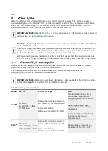
Table 5-1: Serial (COMM) port description
Board
ID: Port
Connector type
Data transfer
rate
(port speed)
Use (connection type)
XFC
G5
J4: COMM1 and
COMM2
Removable terminal
connector (
8 POS
),
screw termination. Wire
gauge 12 AWG to 22
AWG
Baud Rate: 2,400
to 115,200 bps
Remote or local serial
communication for either
RS-232 or RS-485
Communication modules
required to activate port.
XRC
G5
J6-A: COMM 1,
J6-B: COMM 2
Removable terminal
connector (
9 POS
),
screw termination. Wire
gauge 12 AWG to 22
AWG
Same as above
Same as above
IMPORTANT NOTE:
XFC
G5
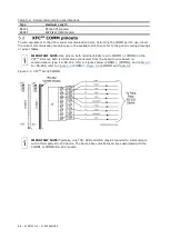
COMM1 and COMM2 connections use pins across both terminal
connector blocks (J4, pins 1-16). XRC
G5
COMM1 and COMM2 connections use pins on J6-A (pins
1-9) and J6-B (pins 1-9) respectively.
Maximum serial communication speed is dependent on the serial interface type and the distance
between the XFC
G5
or XRC
G5
and the connected external device. When installing and wiring external
devices to COMM ports take in consideration the wiring distance limitations as shown in the table
below.
Summary of Contents for XFC G5
Page 25: ...2106026MNAA XSERIESG5 25 ...

