2106026MNAA | XSERIES
G 5
|
51
PI
XFC
G5
XRC
G5
Debounce
Yes, software selectable
from user interface (PCCU): Debounce
can be enabled/disabled on each PI.
Yes, hardware selectable
with onboard pins (J5, J9, J11, J12):
Debounce on
(default): Jumper pins
2-3
Debounce off: Jumper pins 1 and 2
6.1.3
Digital outputs (DO)
Digital outputs (DO) on XSeries
G5
devices are used to control external equipment.
IMPORTANT NOTE:
Analog inputs must be compatible with the external devices they connect
to. Review the external device’s specifications to ensure that the AI can support the device’s
output signal type and range.
6.2.1
XFC
G5
AI
The XFC
G5
has two onboard analog inputs. Each AI consists of an input signal pin and an input ground
pin.
Determine which AI to use and refer to the pinout table for wiring.
IMPORTANT NOTE:
The XFC
G5
AIs support voltage inputs by default. To support current (4
–
20 mA) inputs, add a 250-ohm resistor across the + and
–
terminals.
See section
for additional information on input mode and range.
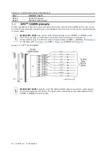
Figure 6-1: XFC
G5
AI terminals
Table 6-4: XFC
G5
AI Pinouts
Input
Pin
Description
AI-1
1
(+) Input signal
(-) Input ground
2
AI-2
3
(+) Input signal
(-) Input ground
6.2.2
XRC
G5
AI
The XRC
G5
has five onboard analog inputs. Determine which AI to use and refer to the pinout table for
wiring.
G5
analog input terminals and the input mode selector jumpers. Use these
jumpers to set the analog input for the type of input signal expected (voltage or current). Follow the
legend to set the correct AI to the correct mode. By default, all analog inputs are set for voltage
inputs (0 -10 V, pins 2 and 3 are jumpered). See
on input mode and range.
Summary of Contents for XFC G5
Page 25: ...2106026MNAA XSERIESG5 25 ...


