background image

PRODUCT MANUAL

VMS - LV modular system

XLP-BB

2C

D

C

50

82

0

0

D

0

11

R

ev

 B

Summary of Contents for XLP-BB

Page 1: ...PRODUCT MANUAL VMS LV modular system XLP BB 2CDC508200D0111 Rev B ...

Page 2: ...Contents 1 Icons 3 2 Material 4 2 1 Material included 4 2 2 Material not included 4 2 2 1 Accessories 4 3 Assembly steps 5 Additional drawings and instructions can be found in the ABB Library 2 ...

Page 3: ...1 Icons Icon Description Warning Caution Note Material included Material not included Tools Tightening torque Nm 3 ...

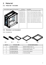
Page 4: ...60mm BB 250 400A for DIN00 D top VMS 63V w 60mm BB 250 400A for DIN00 D bot VMS 63V w 60mm BB 400A for DIN1 3p top VMS 63V w 60mm BB 400A for DIN1 3p bot VMS 64V w 60mm BB 400A for DIN1 3p top VMS 64V w 60mm BB 400A for DIN1 3p bot VMS 43H w 60mm BB 250 400A for DIN00 D 2 2 Material not included 2 2 1 Accessories Nr 1 Nr 2 Nr 3 Nr 4 Nr 5 Item nr Accessory SKU Accessory Description 1 2CPX062374R999...

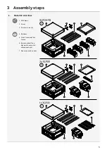
Page 5: ...3 Assembly steps 1 Material overview 1 VMS base 2 Cover 3 Cover screws 4 4 Busbars 5 Front frame or Trim frame 6 Bus mounted fuse base or Fuse switch disconnector s 7 Reserve section cover 5 ...

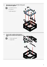
Page 6: ...then the top part of the busbar supports 1 Cover plate screws 4x 2 IP cover plate 3 Busbar supports 2x 3 Break walls and place blocks where necessary for busbars with thickness of 5 mm 1 Busbar support walls 2 Busbar blocks 1 2 6 ...

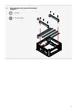
Page 7: ...4 Place busbars and remount the busbar supports 1 Busbars 2 Busbar supports 1 2 7 ...

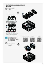
Page 8: ...mm use the following configuration If copper width of PE or N 12 mm use the following configuration remove side panels and break small walls to obtain a 10 mm opening See Installation Instruction of fuse switch disconnectors on how to open the device enabling connections of cables 1 Fuse switch discon nector s 2 Busbars 1 2 A XLP 00 1 A60 60 XLP00 XLP1 1 2 B 8 ...

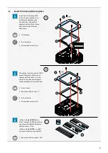
Page 9: ...te screws 4x First place front frame Xx XLP00 around device s then mount reserve section cover Z onto the IP cover plate and reinstall this assembly onto the VMS box 1 Front frame 2 Reserve section cover Z 3 IP cover plate 4 Cover plate screws 4x When using 1x XLP00 use Front frame 1x XLP00 and close opening with adjusted Reserve section covers flat When using 1x XLP1 no addi tional accessories ar...

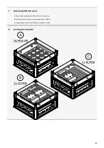
Page 10: ... Fastening VMS box cover 1 Snap cover screws each time in the four corners 2 Fit cover on box one turn on screws max 2 5Nm 3 If necessary stick total isolation symbol on cover 8 Installation complete 10 ...

Page 11: ...ABB Industrial Solutions Belgium bvba Nieuwevaart 51 B 9000 Gent Belgium https new abb com info abb com Tel 32 926 527 77 Copyright 2022 ABB All rights reserved Document number 2CDC508200D0111 Rev B ...

Reviews: