46
Zenith Automatic Transfer Switch | new.abb.com/low-voltage
The Control Connections
The ZT30 and ZBT30 lines of transfer switches are designed
metering modules, and power supplies are mounted
on the Electrical Panel. All terminal connections for the
engine start, switch position contacts, input and output
input and output relays are PCB board mounted on DIN
rail in combinational arrays of 5 inputs and 7 outputs. A
assembly (UTA) power supply for easy reference.
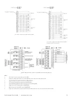
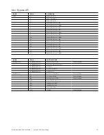
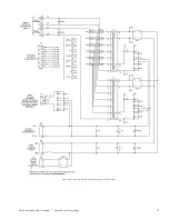
This diagram provides the factory-supplied terminal board
Close-up photographs of an input and output PCB with
terminal connections are shown in Figures S6-13 and S6-14.
For two L cards, there will be two sets of input and output
strips. The maximum combination is three pairs of I/O
strips (that is, a total of six relay DIN rail mounted PCBs).
The controller automatically recognizes the physical location
of the input or output relays via an alpha-numeric
L card exists in the microcontroller, the second PCB-mounted
assembly output relays are named H1 through H5; the outputs
are H7 through H13. Similarly, a third IO_L module is related to
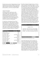
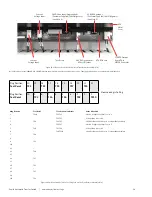
Figure S6-13: Output strip and connection (ABB Zenith part number 50P-3042)
Figure S6-13: Output strip and connection (ABB Zenith part number 50P-3042)
Figure S6-15: MX350 Terminal connection overview
Optional TCP/IP
Ethernet
Switched Power
Supply Allows AC or
DC Control Volage
Reserved
RS485 Communications
Reserved
Expansion Module
Expansion Module
L Card
L Card
L Card
K Card
CT Card
Expansion Module
to Base Unit with a
Single Connector
Three-phase Plus
Ground/Neutral
VT Inputs
Expansion Module
to Base/Expansion Unit
with a Single Connector


