21
Zenith Automatic Transfer Switch | new.abb.com/low-voltage
service and maintain all electrical equipment.
DISCONNECT all power sources prior to installation,
operation, service and maintenance of all electrical
equipment. These activities shall be performed only by
Only use the Charging Handle to perform manual
operations of the Transfer Switch. No motorized
device shall be used as a substitute.
Failure to comply with these instructions
could result in death or serious injury.
Improper Installation
Operation and Maintenance
Bypass Isolation Operation
Sequence of Operations -
Manual Mode - Isolation ATS
Manual operation of the Isolation ATS is only
possible with the front door opened. In the event
the Isolation ATS has to be operated manually in
the AUTO position, please follow these steps:
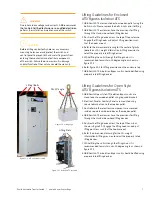
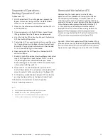
1. Verify that both S1 and S2 contact of the Bypass ATS is
in the Open position. This can be done by opening the
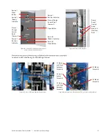
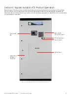
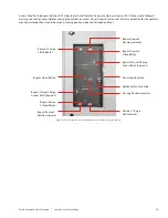
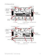
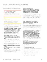
Bypass access panel (refer to figure S5-1). “Open” denotes
contacts are in an open state. “Closed” denotes contacts
are in the closed state.
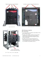
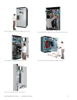
2. If either S1 or S2 contacts are closed, depress the Open
Button at the middle of the Bypass Access Panel (refer to
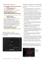
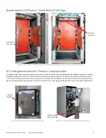
figure S5-2 for location of the Bypass Access Panel).
3. Prior to manually operating the ATS, turn Control Switch
to Inhibit. Refer to figure S5-1 for location of
Control Switch.
4. Open enclosure front door. This will allow access to the
Isolation ATS.
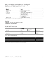
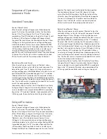
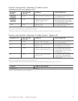
5. Determine contact position status of the ATS. “Open”
denotes contacts are in an open state. “Closed” denotes
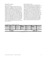
contacts are in the closed state. Refer to table T4-1 for all
possible combination of status indication.
6. A “Ready” status will indicate that the mechanism spring
is charged and that the mechanism could perform transfer
to a particular power source. For instance, S1 “Ready”
indicates that the S1 mechanism spring is charged.
Refer to table T4-1 for all possible combination of
status indication.
7. A
status will indicate that the Isolation ATS is not
ready to perform transfer to a particular power source,
due to mechanism spring not charged.
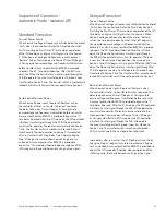
8. To open a closed contact, depressed the Open Button at
the middle of the Isolation ATS.
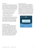
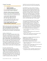
9. To manually charge the closing spring, the Charging
Handle needs to be inserted into the manual charge
access point of the power source to which the Isolation
ATS needs to close onto.
10. With the handle inserted into the appropriate access
point, perform a clockwise rotation to initiate
charging sequence.
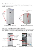
11. Keep rotating the Charging Handle until the closing spring
is fully charged. At this point, the handle will not be able
to be rotated further. Refer to table T4-3 for approximate
number of rotations needed to completely charge
the spring.
12. Once the Isolation ATS indicates a “Ready” status, depress
the Close Button to transfer the ATS to the intended
power source.
Sequence of Operations -
Manual Mode - Bypass ATS
An automatic transfer switch equipped with a bypass-isolation
switch provides the ability to withdraw the Isolation ATS for
testing and/or maintenance purposes without interrupting the
served load. Operations of the unit are quick and convenient
requiring only one operator to complete. Instructions are
mounted on the front of each isolation switch door along
with a mimic panel providing indication of power source
availability and Isolation ATS/Bypass switch positions.
The Bypass ATS is normally open on both sources with the
Isolation ATS feeding the system load. During operation, the
Bypass switch is closed paralleling the Isolation ATS contacts
which then allows withdrawal of the Isolation ATS to the
“TEST” or “ISOLATE” positions. Mechanical and electrical
interlocks are included to prevent cross-servicing or bypassing
to a dead source. In the “TEST” position, the Isolation ATS is
disconnected from the load (now fed through the bypass)
but control power is present to allow complete operational
testing through the control panel of the Isolation ATS. In the
“ISOLATE” position, the Isolation ATS is completely withdrawn
and may be removed from the enclosure for maintenance
if desired. Control power is NOT available in this position.
The Isolation ATS will NOT be operational electrically.
WARNING

