26
Zenith Automatic Transfer Switch | new.abb.com/low-voltage
Closed Transition
service and maintain all electrical equipment.
DISCONNECT all power sources prior to installation,
operation, service and maintenance of all electrical
equipment. These activities shall be performed only by
DO NOT ATTEMPT TO PERFORM MANUAL
OPERATIONS OF AUTOMATIC TRANSFER
SWITCH IN CLOSED TRANSITION MODE.
Only use the Charging Handle to perform manual
operations of the Transfer Switch. No motorized
device shall be used as a substitute.
Failure to comply with these instructions
could result in death or serious injury.
Improper Installation
Operation and Maintenance
ABB Zenith Closed Transition Transfer Switches are designed
to Transfer the Load between two available sources
without interrupting power to the Load (Make-Before-
Break). Paralleling of the two sources occurs within a
100 milliseconds. The initial Source is then disconnected.
Initiating a Closed Transition
When a Test is initiated, the controller initiates the Time
Delay Source 2 Start (Engine Start Timer “P”) cycle. Upon
completion of the (P) time delay, an Engine start Signal is
sent to Source 2. When Source 2 voltage and frequency
reach the preset “Restore” values, the time delay to open
Source 1 timer (W) begins its timing cycle. After the (W) time
delay, the ATS closes into Source 2 only after the controller
ensures the proper phase relationship between the two
Sources. After the ATS closes into Source 2, the SE limit
switch becomes activated. The controller initiates a transfer
signal through the SCR-NO which opens the ATS out of
Source 1. The SNO limit switch activates. The ATS has now
closed into Source 2 position without interrupting the load.
Re-Transfer with Closed Transition
Deactivating the Test Switch initiates the re-transfer.
When Source 1 voltage and frequency reach the preset
“Restore” values, the time delay to open Source 2 timer
(T) begins its timing cycle. After the (T) time delay, the ATS
closes into Source 1 only after the controller ensures the
proper phase relationship between the two Sources. After
the ATS closes into Source1, the SN limit switch becomes
activated. The controller initiates a transfer signal through
the SCR-EO which opens the ATS out of Source 2.
The SEO limit switch activates. The ATS has now closed
back into Source 1 position without interrupting the load.
The ATS defaults to an open transition transfer when
Source 1 fails. Closed transition transfer is not possible
with only one source available. If the optional Transition
Mode Selector (TMS) is available, one can select an Open
Transition Transfer or a Closed Transition Transfer when
both Sources are available. If while in Closed Transition
Mode, the ATS fails to open the source it is attempting to
“transfer out of ” within 100 milliseconds, an Alarm will
sound and the source that the ATS just closed into will be
opened leaving the ATS in its initial source while disabling
all other transfer operations until the problem is corrected
and the “Fail to Open Lockout Reset” has been pressed.
A signal will be provided (STE) to Shunt Trip the Generator
Circuit Breaker if the Transfer Switch remains closed
into both Sources for more than 325 milliseconds. The
load will then be fed by the Source 1. The maximum
time that the two Sources would be parallel, under these
conditions, is less than 500 milliseconds. Before operating
the Closed Transition Transfer Switch, the condition must
be corrected and the Shunt Trip reset. Refer to procedure
for servicing the Switch after Shunt Tripping occurs.
• The unit is Factory set to accomplish transfer within 5
electrical degrees.
• Requires an Isochronous Governor with an operating
frequency of 60+/- 0.2 Hz.
• Requires a Shunt Trip Breaker on the Generator set with a
response time not exceeding 50 milliseconds.
Emergency Service Procedure for Extended Parallel Time
Closed Transition Transfer Switch
If Source 2 breaker shunt trip was triggered after
an extended parallel time (malfunction) occurred.
Follow these steps to open the transfer switch.
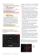
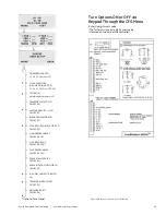
1. Disconnect all power sources by opening all line breakers
(Source 1 and Source 2).
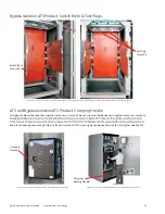
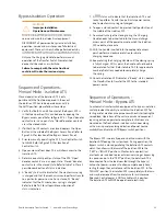
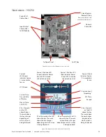
2. With the main door still closed, open the ATS access panel to
expose the various indicators and buttons.
3. Refer to Section 1 – Standalone ATS operations for opening
Source 2 contacts.
4. Once Source 2 contacts are opened, energize Source 1 to
allow the ATS to automatically close back into source 1.
WARNING

