background image

47

Zenith Automatic Transfer Switch     |      new.abb.com/low-voltage

TERMINAL

TERMINAL

TERMINAL

TYPE

G1

H1

I1

Output

G2

H2

I2

Output

G3

H3

I3

Output

G4

H4

I4

Output

G5

H5

I5

Output

G6

H6

I6

Common for outputs

G7

H7

I7

Input

G8

H8

I8

Input

G9

H9

I9

Input

G10

H10

I10

Input

G11

H11

I11

Input

G12

H12

I12

Input

G13

H13

I13

Input

G14

H14

I14

Common for inputs


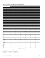
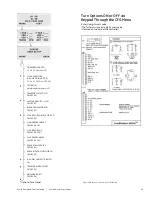
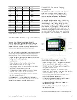
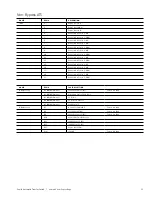
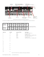
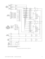
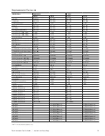
Table T6-2 : IO_L module connections

inputs I1 through I5 and outputs I7 through I13 (see Table T6-2). 

Terminals G7 and G8 are always used for DS and Q2 
functions, respectively, and cannot be adjusted. Depending 
on the type of switch and features ordered, Terminals G1 
through G5 as well as G9 through G13 may not be available 

The MX350 microcontroller is a modular control and monitoring 

•  Flexible control and communication options to suit any low-

voltage transfer switch application.

•  Small footprint.
•  Modular design, which reduces the number of spare 

components for maintenance and testing.

•  Integrated pushbuttons and LED indicators which reduce 

required external components and wiring

•  Multiple communication protocols which permit simple 

integration into monitoring and control systems.

•  A graphical control panel that provides local control and 

access to system information.

Detailed technical information on the MX350 controller is 
described in the manual Entelli Switch 350 Automatic Transfer 
Control System (Publication Number 1601-9071-A1).

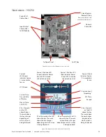
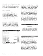
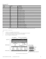
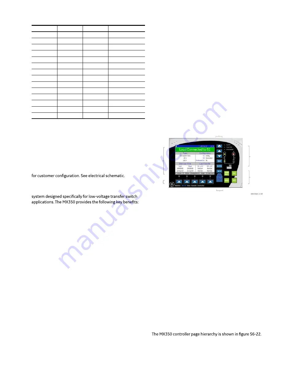
The MX350 Graphical Display  

and Keypad

The MX350 controller features a ¼ VGA color graphical 
display with status LEDs, an USB programming port 
and menu-driven soft keys (see Figure Figure S6-16) 
as well as dedicated control and navigational keys.  

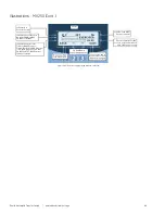
The header bar displays the hierarchical path name, the 
date and time and the current password access level.  The 
soft-key labels are indicated on the bottom line.  Soft-
keys are used for navigation, performing functions and for 
acknowledgement transactions. Soft-keys labels change 
to show relevant selections for the displayed screen. The 
color of each soft-key label indicates its functionality. Soft-
keys are highlighted for the displayed page, unauthorized 
keys are “greyed-out”, and unused keys are not displayed. 

The control panel LEDs summarize the status of the 
transfer switch, including the following indications:
•  ALARM: indicates that there is a problem with the ATS or 

that a user configurable alarm condition is active.

•  TD DELAY: indicates that the controller is timing before 

taking the next control action.

•  XFER INHIBIT: indicates that the controller will not 

automatically transfer to the other source and that operator 
intervention is required to allow transfer.

•  S1 (Source 1) Available LED: indicates that S1 power is 

present and within user defined limits.

•  S2 (Source 2) Available LED: indicates that S2 power is 

present and within user defined limits.

•  S1 (Source 1) Status LED: indicates that the load is 

connected to S1 power.

•  S2 (Source 2) Status LED: indicates that the load is 

connected to S2 power.

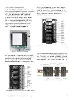
Figure S6-16: MX350 Graphical Display Assembly.  

LED Indicators

Control Keys

Soft-Keys

Graphical
Display

USB Port

Function Keys

Summary of Contents for Zenith ZT30

Page 1: ... OPERATION AND MAINTENANCE MANUAL Zenith ZT30 and ZB30 Short time rated ATS and Bypass Isolation ATS ...

Page 2: ...eeded for Installation and Maintenance 9 Power Cable Connection 9 Section 4 Standalone ATS Operations 10 Sequence of Operations Manual Mode 12 Sequence of Operations Automatic Mode 13 Section 5 Bypass Isolation ATS Operations 18 Sequence of Operations Manual Mode Isolation 21 ATS Sequence of Operations Manual Mode 21 Bypass ATS Sequence of Operations Racking Operations 22 Sequence of Operation Aut...

Page 3: ... voltage Section 6 0 Entelli Switch 250 Controller 28 Section 6 1 Entelli Switch 350 Controller 44 Section 7 Accessories Description 56 List of Major Accessory Items 56 Table T7 1 Troubleshooting and Diagnostics 57 Table T7 2 Replacement Parts List 59 ...

Page 4: ... or variations in hardware and software nor does it provide for every possible contingency in connection with installation operation and maintenance Features may be described herein that are not present in all hardware and software systems ABB Zenith Controls assumes no obligation of notice to holders of this document with respect to changes subsequently made ABB Zenith Controls makes no represent...

Page 5: ...d related accessories in a clean dry location in their original packaging Notice Final inspection of the equipment should be performed prior to energizing the automatic transfer switch as below 1 Remove any dirt or debris that may have collected during shipment or installation NEVER use high pressure blowing air This could drive dirt or other foreign objects into electrical or mechanical component...

Page 6: ...l times is ABB Zenith focus It must be recognized that hazardous voltages and currents can exist during normal operation and any maintenance on the transfer switch must be performed utilizing appropriate safety measures Installation adjustment maintenance or removal of the Priorto installation store the transfer switch in a clean dry location protected from dirt water Provide ample air circulation...

Page 7: ...tect the switch and control panel to prevent dirt and metal fragments from entering the mechanical and electrical components of the switch Failure to do so may result in damage and malfunction of the switch and void the warranty Lifting Guidelines for Open Style ATS Bypass Isolation ATS 1 ABB Zenith Open style ATS Isolation Bypass units are mounted onto a wooden pallet using required brackets 2 El...

Page 8: ...ttp www geindustrial com products critical power 3 For open style units we recommend the door cut out pattern other electrical controls mounting as shown in the dimensional drawings For any questions please contact your local ABB Zenith Service Representative Lifting Provision for Open Style ATS IEC GB Lifting Provision of Open Style ATS 1000A 3000A UL Lower surface of the frame members shall be u...

Page 9: ...le T3 1 Required hand tools for common installation and maintenance tasks Table T3 1 provides a list of hand tools required to perform common installation operation and maintenance of the ZT30 Automatic Transfer Switch Torque values 1 Power cable connectors Referto ATS Fascia Front Cover 2 All other components Consult factory Power Cable Connection AMPERAGE PART NUMBER WIRE RANGE 1000A 2000A 2600A...

Page 10: ...ctrical connections Follow all the warning caution instructions before energizing the unit Operate the switch manually before making the electrical connections Removable Side and Rear Covers Removable Side Covers for Cable and Interlocking Access Removable Rear Covers for Cable Access Options Panel ATS Mechanical Indicator Panel MX Controller HMI Control Switch Options Panel Access Panel Electrica...

Page 11: ...arge Access Point Source 2 Source 2 Position Indicator to ensure a safety condition against paralleling of sources S1 Open and Close Solenoid Assembly S1 Motor Assembly S2 Limit Switch Assembly S2 Motor Assembly S1 Open and Close Solenoid Assembly Figure S4 6 Alternate view of Standalone ATS 3 pole shown without fascia Figure S4 5 View of ATS Intra Panel Interlocks System Figure S4 4 View of ATS p...

Page 12: ...will indicate that the mechanism spring is charged and that the mechanism could perform transfer to a particular power source For instance S1 Ready indicates that the S1 mechanism spring is fully charged Refer to table T4 1 for all possible combination of status indication 5 A status will indicate that the ATS is not ready to perform transfer to a particular power source due to mechanism spring no...

Page 13: ...s theTime Delay Source 2 Start Engine Start Timer P cycle Upon completion of the P time delay an Engine start Signal is sent to Source 2 When Source 2 voltage and frequency reach the preset Restore values the time delay to open Source 1 timer W begins its timing cycle to ensure voltage and frequency stabilization before re transfer A manual pushbutton BYPASS is provided to bypass the W time delay ...

Page 14: ...ed to cancel the test if desired Upon completion of the P time delay an Engine start Signal is sent to Source 2 When Source 2 voltage and frequency reach the preset Restore Values the time delay to Source 2 Timer W begins its timing cycle to ensure voltage and frequency stabilization before transfer A manual pushbutton BYPASS is provided to bypass the W time delay if desired Afterthe W time delay ...

Page 15: ...sequence The delay to open Source 2Timer T begins its timing cycle to ensure voltage and frequency stabilization before retransfer A manual pushbutton BYPASS is provided to bypass the T time delay if desired Afterthe T time delay the MX controller initiates a transfer signal through the Relay Driver Module to operate the main transfer operator The load is now transferred to the Open position The t...

Page 16: ...mit switch activates The ATS has now closed into Source 2 position without interrupting the load Retransfer with Closed Transition Deactivating the Test Switch initiates the re transfer When Source 1 voltage and frequency reach the preset Restore values the time delay to open Source 2 timer T begins its timing cycle Afterthe T time delay the ATS closes into Source 1 only afterthe controller ensure...

Page 17: ...SSIBLE OPERATION On CLOSED Mechanism closing spring is charged Contact set is closed connecting load to source User may manually open the contact set by pushing the Bypass Open Button On OPEN Mechanism closing spring is discharged Contact set is open User may manually close the contact set by pushing the Bypass Source Close Button CLOSED Mechanism closing spring is not charged Contact set is close...

Page 18: ...agram provided forthe electrical connections Follow all the warning caution instructions before energizing the unit Operate the switch manually before making the electrical connections MX Controller HMI Access Panel for Bypass Operations Bypass Switch Annunciation Lights ATS Contact Reset Control Switch Options Panel Figure S5 1 Front view of Bypass Isolation ATS in an enclosure MX350 controller s...

Page 19: ... Manual Charge Access Point Source 1 Bypass Source 1 Close Button Bypass Source 1 Position Indicator Figure S5 2 View of Bypass Access Panel with various indicators and push buttons Access Panel forthe Bypass Isolation ATS is located in the left side the frame assembly as shown in S5 1 Make sure to follow all warning and caution notes before accessing the buttons on access Panel Access Panel consi...

Page 20: ...ce to charge the mechanism manually operate the opening and closing buttons In Bypass Isolation ATS same charging handle needs to use for racking the Isolation ATS Charging Handle Charging Racking Handle Figure S5 3 Location of the switch bank left and Figure S5 4 Test plug assembly right Bypass Isolation only shown with Protective Shutter option Figure S5 5 Location of Charging Handle on the Stan...

Page 21: ...sfer to a particular power source due to mechanism spring not charged 8 To open a closed contact depressed the Open Button at the middle of the Isolation ATS 9 To manually charge the closing spring the Charging Handle needs to be inserted into the manual charge access point of the power source to which the Isolation ATS needs to close onto 10 With the handle inserted into the appropriate access po...

Page 22: ... closed The Bypass ATS needs to close into the same source as that of the Isolation ATS s 6 An illuminated Status LED green will indicate that the mechanism spring is charged and that the mechanism could perform transfer to a particular power source Refer to table T4 2 for all possible combination of status indication 7 A Status LED green that is not illuminated will indicate that the Bypass ATS i...

Page 23: ...he ATS is in the AUTO position press the ATS Contact Reset button This will make sure the Isolation ATS closes its contacts to the same Source as the Bypass ATS 9 At this point proceed to open the Bypass ATS contacts by pressing the Open button via the Bypass Access Panel 10 Rotate the Control Switch to the Auto position 11 ATS is now fully automatic Notes 1 Control Switch in Inhibit will prevent ...

Page 24: ...via the Bypass Access Panel Figure S5 8 Operator pulling Isolation ATS out to be serviced Figure S5 9 Position of the Isolation ATS priorto removal Figure S5 10 Application of lifting provisions onto the Isolation ATS priorto removal Figure S5 11 Removal of the Isolation ATS out from the Bypass system ...

Page 25: ...allen below the preset Fail values the controller initiates the Time Delay Source 2 Start Engine Start Timer P cycle Upon completion of the P time delay an Engine start Signal is sent to Source 2 When Source 2 voltage and frequency reach the preset Restore values the time delay to open Source 1 timer W begins its timing cycle to ensure voltage and frequency stabilization before re transfer A manua...

Page 26: ...t switch becomes activated The controller initiates a transfer signal through the SCR EO which opens the ATS out of Source 2 The SEO limit switch activates The ATS has now closed back into Source 1 position without interrupting the load The ATS defaults to an open transition transfer when Source 1 fails Closed transition transfer is not possible with only one source available If the optionalTransi...

Page 27: ... Box H Customer I O I Engine Start Terminals J Voltage Output Fuse Block for Customer Use A Control PowerTransformers B Controller SPD C Electrical Panel Input D Maintenance Switch E Relay Driver Module F I O Modules G MX350 Controller I Engine Start Terminals J Voltage Output Fuse Block for Customer Use H Customer I O Figure S5 12 Front view of MX350 Electrical Panel Figure S5 13 Front view of MX...

Page 28: ...rol Connections The engine start relay is located on the Electrical Panel as indicated in Figure S5 13 Terminals on the relay base can be accessed for manual transfer switches or in other applications not requiring the microprocessor contacts and the A4 Source 1 auxiliary contacts are also provided These terminals are clearly marked and appear on the left side of the Electrical Panel item H in Fig...

Page 29: ...e rating Figure S6 2 Entelli Switch 250 front display 1 Unlock the enclosure 2 Open the enclosure 3 Place the Control Switch in the Inhibit 4 Close the external up stream Source 1 circuit breaker NOTES Source 1 Available and Source 1 Position LED s will illuminate If Source 1 Available LED does not illuminate verify that Source 1 Voltage is above the preset restore value The Gen Set will start and...

Page 30: ...erface to in conjunction with LCD screen 1 Setting sensors and timers II The Controls Power Supply CPS Contains transformers which drop line voltage to control level for controller input LCD Keypad These options are accessible through the LCD and keypad loaded into a particular unit scrolling through the SET and CFG menu will show the descriptions of the options see options The SET setting menu is...

Page 31: ...rVoltage Fail Factory Default 110 This adjustment determines the maximum acceptable Over Voltage Adjust via the SET menu Range is 105 to 110 timer will be bypassed to expedite the transferto Source 1 OverVoltage Restore Factory Default 105 This adjustment determines the minimum acceptable OverVoltage threshold at which the transfer switch is allowed to transferto Source 2 Adjust via the SETmenu Re...

Page 32: ...adjustable Engine exercise timer Exercise duration can be set between 5 and 60 minutes in 1 minute increments Can be is 20minutes When exerciser is impending E appears in CTAP Alarm Panel on transferto Source 2 with Silence button Control Switch Inhibits controllerfrom transferring for maintenance and troubleshooting Maintenance Switch Removes powerfrom control circuit for maintenance and troubles...

Page 33: ...nconsistent phase rotation between the sources WARNING R26 Interruptable Power Rate Provisions Allow transfer out of Source 1 position to Source 2 or dead Source 2 Alarm and Pre Signal circuit included R50 Not available on delayed transition ATS In Phase Monitorthis feature restricts Live to Live Source Transfers to occur unless both Sources are within 7 electrical degrees or less of each other li...

Page 34: ...of Source 1 or Source 2 to be the Prime Source Transfer Switch will transferto selected Prime Source if that Source is available Keyed or non keyed operation available T Time Delay S1 Source 1 StableTimer To delay transferto Source 1 immediate retransfer on Source 2 failure Adjustable 0 60 minutes in 1 second increments Standard setting is 30 T3 W3 Elevator Pre Signal Auxiliary Contacts Open 0 60 ...

Page 35: ...attery part K 4100 Battery will last 5 years and provides powerto retain clock function only Controllerfunctions without battery CDT One Event Timer Exerciser Load No Load One event Exerciser with adjustableTimer Exercise duration can be set between 5 and 60 minutes in 1 1 7 14 or 28 days Factory default is 20 minutes the Timer Exerciser 1 Beginning from the S1 OK screen press MORE then CFG 2 Pres...

Page 36: ...te the Engine cool down cycle if the CDT Exerciser is Factory configured for a No Load Exerciser or allow the controller to complete retransfer to Source 1 if the CDT Exerciser is Factory configured for a Load Exerciser How to Bypass the Next Exercise Event and Keep the Rest of Scheduled Events Unchanged 1 Press Test 2 Press MORE Press BYPASS EXER To re institute the next exercise event back press...

Page 37: ...down keys Press SAVE after each entry to save value and to move to the next value to be changed 7 Press BACK when complete 8 Press MORE repeatedly until SET USER SETUP Press BACK then ESC to the S1 OK screen How to Bypass Cancel an Exercise During an Exercise Cycle 1 Press BPASS 2 Allow the controller to complete the Engine cool down cycle Exercise or allow the controllerto complete retransferto H...

Page 38: ...trol Switch Maintenance Switch DT DW E EL P J2E J2N K P L1 P L2 P L3 P L4 P LN P P1 Q2 Q3 Q7 R1 3 R8 R15 R16 R50 S5P S12 P S13 P T T3 W3 U UMD VI W YEN Standard Accessory included in the group package Optional Accessory not included but can be added to the group package Optional Accessory Can not be used with accesory having the same symbol Delayed Transition Units Only T6 1 MX 250 Accessory Matri...

Page 39: ... Event Impending SET Menu Keypad 4 orthe word on the LCD above the key The word above the key changes depending on which screen is being displayed 2 orthe word on the LCD above the key The word above the key changes depending on which screen is being displayed 1 orthe word on the LCD above the key The word above the key changes depending on which screen is being displayed Menus More CFG TEST Curre...

Page 40: ...ciser Time Day forWEEKLY Exerciser Time Date Month for 14 DAY 28 DAY and 365 DAY Exerciser 24 Hour System Indicates of Exerciser Periods Indicates type of Exerciser DAILY WEEKLY 14 DAY 28 DAY or 365 DAY Up and Down Use to change values Cursor To save value and to move cursorto next Load No Load CDP Exercise Indicator Exercise duration forthis event in hours and minutes up to 10 hours per event ...

Page 41: ...LTAGE R1 1 OR R1 3 ON OFF 22 S1 UNDER FREQUENCY ON OFF 20 22 S2 OVER VOLTAGE ON OFF 20 21 S2 OVER FREQUENCY ON OFF 20 22 PHASE IMBALANCE VI ON OFF 24 PHASE ROTATION MATCH R16 ON OFF 23 LOAD DISCONNECTTD UMD 24 TRANSFER ALARM CTAP ON OFF 21 NETWORK ZNET ON OFF 24 Turn Options ON or OFF via Keypad Through the CFG Menu Enter six digit access code The factory assigned six digit access code is located ...

Page 42: ...ENCY 20 Fail Restore SETPHASE IMBALANCE VI FAIL 5 RESTORE 3 24 SETPHASE IMBALANCE VI TIME DELAY 30 seconds 24 TIME DELAY S2 START P1 22 TIME DELAY S2 STABLE W 24 LOAD PRESIGNAL TD T3 W3 24 LOAD DISCONNECTTD UMD 24 ATS OPENTIME TO S2 DW DELAY units only 21 TIME DELAY S1 STABLE T 24 ATS OPENTIME TO S1 DT DELAY units only 21 S2 STOP DELAY U 24 CALIBRATE S1 21 CALIBRATE S2 21 Optional Accessories Chan...

Page 43: ...matic Transfer Switch new abb com low voltage View System Data Enter six digit access code The factory assigned six digit access code is located on the back of the controller Figure S6 8 System Data View on the MX250 ...

Page 44: ... brush 11 Make sure that all covers and barriers are installed and properly fastened Engine Start Control Connections The engine start terminals are located on the Electrical Panel as indicated in Figure S6 9 These terminals can be accessed for manual transfer switches or in other applications not requiring the microprocessor contacts and the A4 Source 1 auxiliary contacts are also provided These ...

Page 45: ...age The S2 LED should be illuminated Electrical parameters including phase rotation can be viewed on the Graphical Control Panel on the Value Summary and Diag Phasor screens 9 Verify that the phase rotation of Source 1 is the same as the phase rotation of Source 2 10 Manually shut down the generator via controls on the generator itself Checking the Switch s Ability to Transfer 11 Turn the Control ...

Page 46: ... is three pairs of I O strips that is a total of six relay DIN rail mounted PCBs The controller automatically recognizes the physical location of the input or output relays via an alpha numeric L card exists in the microcontroller the second PCB mounted assembly output relays are named H1 through H5 the outputs are H7 through H13 Similarly a third IO_L module is related to Figure S6 13 Output stri...

Page 47: ...ad The MX350 controllerfeatures a VGA color graphical display with status LEDs an USB programming port and menu driven soft keys see Figure Figure S6 16 as well as dedicated control and navigational keys The header bar displays the hierarchical path name the date and time and the current password access level The soft key labels are indicated on the bottom line Soft keys are used for navigation pe...

Page 48: ...adiness forthe engine generator set is tested It does not test the functionality of the Automatic Transfer Switch itself In the Gen Start and Transfer mode the controller starts the engine and actually transfers the load to the alternative source This mode can be used to test the integrity of the emergency power system It can also be used to setup a schedule fortimes of operation when the switch l...

Page 49: ...mbly UTA The power supply is termed universal because the same unit handles all line voltages from 120Vac through 600Vac via an internal six position jumper array Figure S6 23 shows the external connections points forthe UTA The UTA also features a 120Vac uninterruptible power supply input and 24Vdc input battery options 120Vac and 24Vdc ungrounded must be supplied togetherfrom an uninterrupted po...

Page 50: ...ts drawn in dashed lines are option package and customer connections of the transfer switch 3 4 5 6 Engine start contact is rated 10 Amps at 28VDC 120VAC 7 Output strip contacts are rated 10 amps at 30VDC 250VAC 8 Engine start contact may be on separate terminal block for bypass switches Referto electrical schematic forterminal location ABB ZENITH CONTROLS ABB ZENITH CONTROLS ABB ZENITH CONTROLS A...

Page 51: ...to Source 2 NO 15 Connected to Source 2 COM 16 Connected to Source 2 NO 17 Connected to Source 2 COM Non Bypass ATS NAME ITEM FACTORY SETTING G Output Strip G 1 NO NC Common Load Shed from S2 R15 Factory Use Only G 2 NO NC Common Alternative Source Fail to Start G 3 NO NC Common S1 Failure G 4 NO NC Common S2 Failure to Connect G 5 NO NC Common Load Control 1 G Output Strip G 7 Disconnect Switch D...

Page 52: ... 1 COM 11 Connected to Source 2 NO 12 Connected to Source 2 COM 13 Connected to Source 2 NC 14 Connected to Source 2 NO 15 Connected to Source 2 COM 16 Connected to Source 2 NO 17 Connected to Source 2 COM 18 Connected to Source 1 Bypass NO 19 Connected to Source 1 Bypass COM 20 Connected to Source 2 Bypass NO 21 Connected to Source 2 Bypass COM Bypass ATS Contacts will not be active on Bypass Uni...

Page 53: ...Faults Control Phase A Phase B Phase C Phase A Phase B Phase C Phase A Phase B Phase C Virtual Events Zenith Waveform Datalog Summary V Inputs V Outputs I Harm Message Reset Values Inputs Outputs System Setpoints Operation Control Security Flex Events Reset Diag Stats Phases About Info Exerciser Main Menu Level 1 Level 3 Level 2 Setup Test ExerCancel Report Waveform Datalog PQ Figure S6 22 MX350 S...

Page 54: ...C to Output from Source 1 to Input Output Relays 4 TP6 TP7 Line AC Voltage Input from Source 2 5 TP6 TP7 TP8 Voltage Drop Across R2 6 TP9 TP10 24 VAC to Output from Source 2 to Input Output Relays 7 TP4 8 9 TP2 10 11 12 TP9 13 14 TP7 15 16 TP5 17 18 TP3 19 20 TP1 Plug Position Test Point 20 TP1 19 18 TP3 17 16 TP5 15 14 TP7 13 12 TP9 11 Plug Position Test Point 10 9 TP2 8 7 TP4 6 5 TP6 4 3 TP8 2 1...

Page 55: ...55 Zenith Automatic Transfer Switch new abb com low voltage Figure S6 25 UniversalTransformer Box Assembly UTA Schematic ...

Page 56: ...nected before installing accessories A Protective Shutter Assembly Protective Shutter Assembly Installation Instruction drawing O 4105 is needed for this installation procedure For field installation the Isolation ATS needs to be removed to provide sufficient working area Refer to Section 3 under LIFTING AND MOUNTING GUIDANCE ATS for lifting instructions B Wire Harness for Inverted Option Consult ...

Page 57: ...Mechanical issues 1 Determine source availability 2 Control Switch should be in Auto Mode 3 Check controller indicator status This needs to be consistent with mechanical indicator via the ATS access panel 4 Determine Status and Contact position of ATS This can be performed by opening the ATS access panel of the enclosure or observing via the fascia 5 Refer to table T1 1 for interpretation of Statu...

Page 58: ...peration inhibited Check if Racking Solenoid is preventing racking operation Forthe Racking Solenoid to allow racking operation Power source availability check controller indication Maintenance Switch on Electrical Panel S5 12 and S5 13 Bypass ATS is closed into either source Isolation ATS is in between the Isolate and Auto position Control Switch is in the INHIBIT position If above conditions are...

Page 59: ...ransformer 460V 575V 9T58K0070 9T58K0070 9T58K0070 9T58K0070 Control Transformer Multi Tap 9T583718 9T583718 9T583718 9T583718 Fuse 30A 600VAC KTK 30 KTK 30 KTK 30 KTK 30 Fuse Block USM2 USM2 USM2 USM2 Fuse Block USM3 USM3 USM3 USM3 MOV assembly 26P 3161 26P 3161 26P 3161 26P 3161 Operator with green cover P9XPLVGD P9XPLVGD P9XPLVGD P9XPLVGD FV PT LED lamp 24V P9PDTVDLV P9PDTVDLV P9PDTVDLV P9PDTVD...

Page 60: ...P 3045 50P 3045 Contact lubricant MM 602 MM 602 MM 602 MM 602 Multi purpose lubricant MM 600 MM 600 MM 600 MM 600 Table T7 2 cont Recommended spare parts List ABB Zenith Controls Inc 305 Gregson Drive Cary NC 27511 24 hour support ABB Technical Services 1 800 637 1738 epis pqservice abb com new abb com low voltage 1SCC303035M0201 08 19 DEA 585A ...

Reviews: