57
Zenith Automatic Transfer Switch | new.abb.com/low-voltage
SYMPTOM
ANNUNCIATION
POSSIBLE CAUSE(S)
TROUBLESHOOT STEP 1
ACTIONS TO BE TAKEN
ATS will not
transfer
to SOURCE 1
SOURCE 1
Source 1 voltage or frequency not
within acceptable parameters
Check utility and utility breaker
Notify factory of the conditions of all
Status and Contact position indication.
are allowed to perform further
troubleshooting tasks.
None
Power supply connector unplugged
Plug in connector
ATS will not
transfer
to SOURCE 2
SOURCE 2
Source 2 voltage or frequency not
within acceptable parameters
Check: Engine Start Connections,
Generator Breaker, Generator Output ,
and Engine Control Switch
None
Power supply connector unplugged
Plug in connector
Engine does
not START
SOURCE 2
Engine start wires not
terminated properly
Check engine start connections
Generator is in OFF position
Investigate why Engine Control
Engine does
not STOP
LCD Display - “TD
Engine Cool Down”
U timing cycle not complete
Check U timer setting
SOURCE 1
POSITION,
and SOURCE 1
and SOURCE 2
AVAILABLE LEDs
on, but U timer has
timed out
Engine start wires not
terminated properly
Check engine start connections
Generator in MANUAL
Place generator in AUTO
ATS will not
transfer
electrically to
intended source
LCD Display
“EXPECT SN
ACTUAL SE”
or “EXPECT SE
ACTUAL SN”
Mechanical issues
1. Determine source availability.
2. Control Switch should be in Auto Mode
3. Check controller indicator status. This needs
to be consistent with mechanical indicator
via the ATS access panel.
4. Determine Status and Contact position
of ATS. This can be performed by opening
the ATS access panel of the enclosure or
observing via the fascia.
5. Refer to table T1-1 for interpretation of Status
and Contact position indication.
Incorrect position of the Bypass
Isolation ATS
Check if Isolation ATS is in the Auto position. This
can be determined via the Status Annunciation
Rack into Auto position. Validate with
Status Annunciation Lights.
ATS will not
transfer
manually to
intended source
LCD Display
“EXPECT SN
ACTUAL SE”
or “EXPECT SE
ACTUAL SN”
Mechanical issues
1. Determine source availability.
2. Control Switch should be in Auto Mode
3. Check controller indicator status. This needs
to be consistent with mechanical indicator
via the ATS access panel.
4. Determine Status and Contact position
of ATS. This can be performed by opening
the ATS access panel of the enclosure or
observing via the fascia.
5. Refer to table T1-1 for interpretation of Status
and Contact position indication.
DANGER: Due to mechanical interlocking,
manual close operation will only be allowed if the
opposite source is open.
Notify factory of the conditions of all
Status and Contact position indication.
are allowed to perform further
troubleshooting tasks.
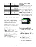
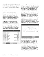
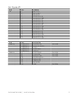
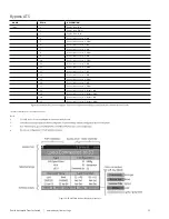
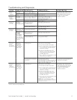
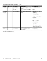
Table T7-1: Troubleshooting and diagnostics
Troubleshooting and Diagnostics

