44
Z E N ITH Z TG ( D/C T ) T-S E R I E S 16 0 0 -3 0 0 0 A
1
LC
D
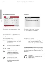
The small icons in System Overview
-pages are:
On upper right corner
Indicates the amount of pages
and the page where you are at
the moment
Auxiliary voltage connected
11:06 Time
Application set up as
Transformer-Generator.
Generator start-up signal
deactivated
Application set up as
Transformer-Generator.
Generator start-up signal
activated
On upper left corner
60s
Time delay, in Alarm list you can
see the name of delay at the
same time, e.g. Override S1 Fail
—
Fig. 4.3 Location of the small icons and the alarms
—
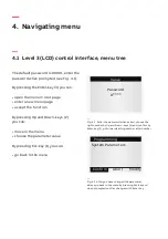
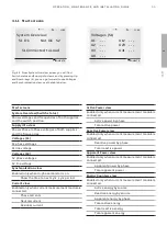
Fig. 4.4 When pressed Esc-key (1) in System
Overview -pages, the alarm list is shown.
Alarm List
Description of the icons
System Overview
S1 Ok Not Ok S2
11:06
S1 Connected to Load
Override S1 Fail
60s
Alarm List
Invalid Date
Ethernet disconnected
On the lower edge
of the screen you can
see the Alarms. When pressed Esc-key (1)
in System Overview -pages, the alarm list
is shown.
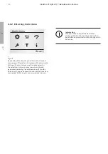
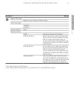
Information
The default values are marked in the menu
tree by *-marking.
TruONE ATS
Summary of Contents for Zenith ZTG T Series
Page 2: ...2 1 ZENITH ZTG D CT T SERIES 1600 3000 A ...
Page 6: ...6 1 ZENITH ZTG D CT T SERIES 1600 3000 A ...
Page 10: ...10 1 ZENITH ZTG D CT T SERIES 1600 3000 A ...
Page 38: ...38 1 ZENITH ZTG D CT T SERIES 1600 3000 A ...
Page 60: ...60 ZENITH ZTG D CT T SERIES 1600 3000 A 1 LCD ...
Page 104: ...104 1 ZENITH ZTG D CT T SERIES 1600 3000 A ...
Page 116: ...2 116 ZENITH ZTG D CT T SERIES 1600 3000 A ...
Page 120: ...2 120 ZENITH ZTG D CT T SERIES 1600 3000 A ...
Page 123: ...123 1 OPER ATION MAINTENANCE AND INSTALL ATION GUIDE ...


