63
1
O PER AT I O N , M A I N T EN A N C E , A N D I N S TA L L AT I O N G U I D E
—
5.2 Using Ekip Programming -module
—
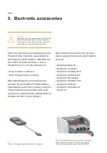
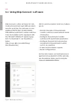
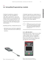
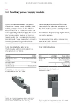
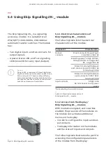
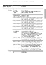
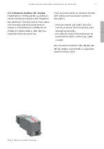
Fig. 5.4 Ekip Programming -module
—
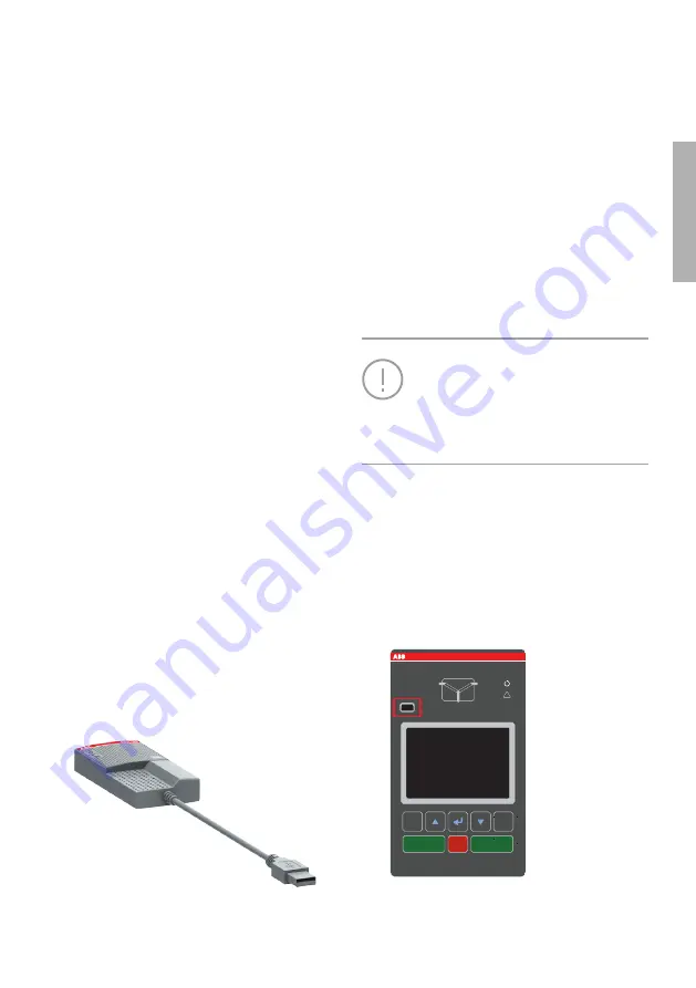
Fig. 5.5 Programming port (USB port) is
situated in the front of the HMI, on left side
The Ekip Programming -module is
suitable to use with all ZTG(D/CT)
1600-3000 A,208-480 Vac automatic
transfer switches. You can connect the
module via the programming port, see
Fig. 5.6. The programming port is only
compatible for use with Ekip Program-
ming -module.
Ekip Programming -module allows you to:
• With Ekip Connect software update the
software and load, set and read the pa-
rameters
The Ekip Programming -module draws its
power from the PC and connects one side
directly to the programming port (see Fig.
5.6) and on the other to the USB port of
the PC with the cable supplied.
Notice
Ekip Programming only powers the controller
board (HMI and external modules excluded).
Therefore, in order to identify all connected
parts with Ekip Connect, the auxiliary power
supply module, type OXEA1, must be used
(see chapter 5.4).
5.2.1 LED indications
Ekip Programming -module turns on after
connecting to the PC, and is equipped
with two LEDs. The first, illuminates
green indicating that the module is on,
and the second, illuminates yellow indi-
cating active communication.
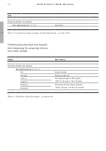
l
ON
ll
ON
Auto
Alarm reset
AUTO
!
S1
S2
LOAD
l
ll
O
O
OFF
Esc
Summary of Contents for Zenith ZTG T Series
Page 2: ...2 1 ZENITH ZTG D CT T SERIES 1600 3000 A ...
Page 6: ...6 1 ZENITH ZTG D CT T SERIES 1600 3000 A ...
Page 10: ...10 1 ZENITH ZTG D CT T SERIES 1600 3000 A ...
Page 38: ...38 1 ZENITH ZTG D CT T SERIES 1600 3000 A ...
Page 60: ...60 ZENITH ZTG D CT T SERIES 1600 3000 A 1 LCD ...
Page 104: ...104 1 ZENITH ZTG D CT T SERIES 1600 3000 A ...
Page 116: ...2 116 ZENITH ZTG D CT T SERIES 1600 3000 A ...
Page 120: ...2 120 ZENITH ZTG D CT T SERIES 1600 3000 A ...
Page 123: ...123 1 OPER ATION MAINTENANCE AND INSTALL ATION GUIDE ...

