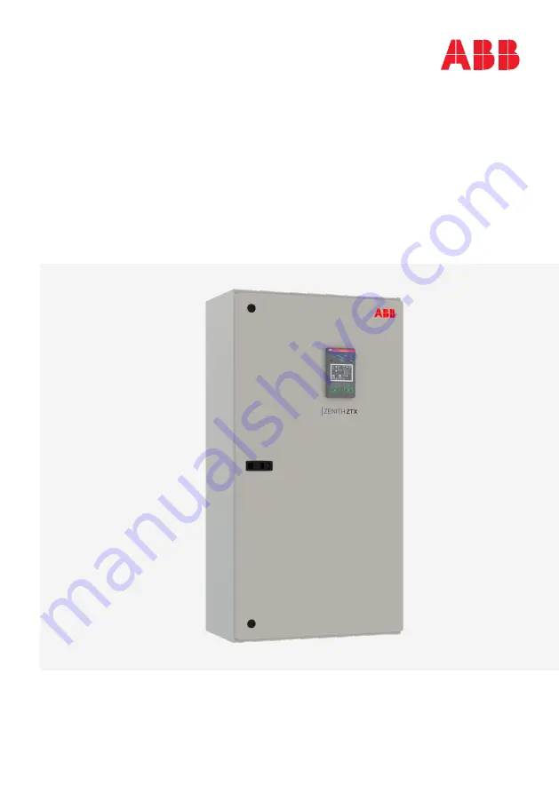
background image

QUICK STA RT GUIDE 

Zenith ZTX series

Enclosed ATS, 30-1200 A, 200-480 Vac


This document is not intended to replace document 1SCC303022M0201, ZTX series O&M, 
which is called out in some cases for further detail. This quick start guide is intended to 
help the user power the ATS and make it fully operational with a few simple steps.

Summary of Contents for Zenith ZTX Series

Page 1: ...0 480 Vac This document is not intended to replace document 1SCC303022M0201 ZTX series O M which is called out in some cases for further detail This quick start guide is intended to help the user power the ATS and make it fully operational with a few simple steps ...

Page 2: ... connections 9 Place for Ekip modules communication signaling and connectivity modules 10 Auxiliary contact block mounting location 11 The product identification label 12 Programming port only for Ekip Programming module and Ekip Bluetooth modules About your ZTX series ATS Zenith ZTX series construction Zenith ZTX series ATS consists primarily of the TruONE power panel and an electrical enclosure ...

Page 3: ...U 20 f 10 0 1 2 3 4 5 10 15 20 30 S1 Failure delay s S1 Return delay min On Off Auto config Start Ok Priority No priority Source 1 In phase monitor Off On AUTO S1 S2 LOAD l ll With Ekip Programming module and a laptop with Ekip Connect software you can view status set operational parameters and configure generator exercisers on the ATS even without any line voltage or auxiliary power connected to ...

Page 4: ...le 1 Figure 3 Note Auxiliary contacts are very difficult to remove once applied Auxiliary contacts will be shipped loose Use Table 1 and Figure 3 to apply A NO and B NC contacts for correct operation Each source has two separate mounting points capable of holding up to two aux contacts each for position indication for a total of four per source There is no restriction on using NO NC or both in any...

Page 5: ...label matches the installed application For location see Figure 1 number 12 3 Confirm that cables are connected properly and torqued according to label the ATS labeling 4 Verify that the enclosure ground connection is properly terminated 5 Confirm that control wiring for engine start is properly terminated to the engine start contact located in Figure 1 number 8 6 Additionally connect all applicab...

Page 6: ...toggles between Manual and Auto modes 6 I ON Operate switch to I position 7 II ON Operate switch to II position Slide switch Figure 1 number 4 must be in Auto and controller mode Figure 3 number 5 must be in Manual Lamp test l ON Off load test ll ON Auto Alarm reset On load test Bypass time delay Dropout U f Manual retransfer Generator stop delay 4 min 30 s U 5 f 5 U 10 f 5 U 15 f 10 U 20 f 10 0 1...

Page 7: ...is initially energized This function recognizes the electrical system then automatically sets all the system parameters system voltage frequency and phase sequence 5 flashes in 1 s 5 flashes in 1 s Complete System settings set 1 2 3 4 Auto Configure Figure 5 ...

Page 8: ...uration for generator after S1 restoration Settings Optional Default settings on the ATS are as shown in Figure 6 To alter settings simply adjust the position of the dip switches accordingly Generator exercisers must be programmed through Ekip Connect 3 with Ekip Programming module Lamp test Off load test Auto Alarm reset On load test Bypass time delay Dropout ΔU Δf Manual retransfer Generator sto...

Page 9: ...nitor Off On AUTO S1 S2 LOAD l ll Confirm Automatic Operation To put your ATS into Auto mode confirm the slide switch is in AUTO before the enclosure door is closed This slide switch overrides the Auto Manual mode set from the HMI To place ATS controller in auto mode press the auto key on the HMI as in Figure 7 If already in Auto mode pressing this key will take the switch out of Auto mode Confirm...

Page 10: ...ary source Verify the ATS switches to the backup source according to set point and time delay parameters Re connect the supply to the primary source If the ATS returns to primary source as expected the ATS function in Auto is validated Lamp test l ON Off load test ll ON Auto Alarm reset On load test Bypass time delay Dropout U f Manual retransfer Generator stop delay 4 min 30 s U 5 f 5 U 10 f 5 U ...

Page 11: ... Additional information Manual and automatic operation TruONE ATS Video https www youtube com watch v bosvSPVi2sM https www youtube com watch v qV2KoIv38GY Installation of accessories TruONETM ATS Video ...

Page 12: ...served Specifications subject to change without notice 1SCC303022K0201 19 10 ABB Zenith Controls Inc 305 Gregson Drive Cary NC 27511 24 hour support ABB Technical Services 1 800 637 1738 epis pqservice abb com http solutions abb zenith ...

Reviews: