background image

Architectural Kitchen Range Hoods


P.O. Box 215 Bodega Bay,

 CA 94

923

 (

800

5

48-

3932

 Fax (

800

5

48-

3930

E-mail: 

web

mail@abbaka.com  http://www.abbaka.com

Page 2

IA-031 8/03

Model Number:  HY

EX

-1.0K/HY

EX

-1.4K

Maximum CFM:  1000 CFM/1400 CFM
Volts:  115VAC
Hertz:  60 Hz
Amps: 

3.3

 Amps

Required Duct Size:

HY

EX

-1.0K:    8” Round (51 sq. in. equivalent)

HY

EX

-1.4K:  10” Round (80” sq. in. equivalent)

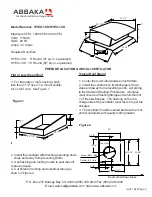
Flat or Low Slope Roof

1.  For flat roofs or roofs having a pitch
less than 1 1/2” rise in 12, mount ventila-
tor on roof curb.  See Figure 1.

2"

23"

25 5/8"

2.  Install the ventilator with discharge pointing down
     slope and away from prevailing winds.
3.  Use flashing and roofing mastic to seal the unit
to prevent leaks.
4.  Cut holes for ducting and electrical wiring as
shown in Figure 2

Figure 1

Typical Roof Mount

1.  Center the duct cutout between roof rafters.
2.  Install the ventilator so its discharge is down
slope and away from prevailing winds.  According
to the Standard Roofing Procedures:  (shingles
must cover rear flashing flange and a minimum of
1’ of the side flanges.  The flashing on the dis-
charge side of the ventilator must rest on top of the
shingles.
3.  The ventilator must be sealed between the roof
and its underside with quality roofing mastic.

Figure 2

PREPARE LOCATION & INSTALL VENTILATOR

9"

25 5/8"

22 13/16"

7"

26 1/2"

12 3/4"

11 1/2"

7 1/2"

4 1/4"

25 5/8"

23"

26 1/2"

Cut-out: Ø9" or Ø11 in

Cut-Out:  Ø1 1/4 in

Top View

22 13/16"

Roof or Wall Down Slope

Summary of Contents for Hy-Ex 1.0K

Page 1: ...vent back drafting Follow the heating equipment manufacturers guideline and safety standards such as those published by the National Fire Protection Association NFPA and the American Society for Heating Refrigeration and Air Conditioning Engineers ASHRAE and the local code authorities 5 When cutting or drilling into wall and ceiling do not damage electrical wiring and other hidden utilities 6 Duct...

Page 2: ...3 Use flashing and roofing mastic to seal the unit to prevent leaks 4 Cut holes for ducting and electrical wiring as shown in Figure 2 Figure 1 Typical Roof Mount 1 Center the duct cutout between roof rafters 2 Install the ventilator so its discharge is down slope and away from prevailing winds According to the Standard Roofing Procedures shingles must cover rear flashing flange and a minimum of 1...

Page 3: ...equired duct size 2 Tape all joints with duct tape 3 Turn on power and check ventilator operation 4 Make sure damper opens and closes freely WARNING Turn off power at the service box before wiring 1 Power supply for the ventilator is 115V AC 60 Hz See page 2 for specifications 2 Run electrical cable between the ventilator and the range hood or ventilator and wall switch See Figure 3 3 Remove top e...

Page 4: ... Claims for damages or shortages must be reported within ten 10 days of receipt of products s For any product s received damaged by the forwarding agent THE FOLLOWING INSTRUCTIONS MUST BE FOLLOWED 1 For products delivered by UPS a Concealed Damages Keep all cartons and fillers Call UPS for an inspection and notify ABBAKA immediately b Visible Damages Save all cartons and fillers and file complaint...

Reviews: