background image

10 

Wiring At the Hood: 

1. 

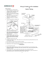
Position hood liner on counter below hood. 

2. 

Remove Light /Switch Control Panel and  Light 
Only Panel (or Screw Covering Panel in wall 
mount hood) from liner (see Figure A). 

3. 

Feed conduit from service panel into knock out 
labeled “Power Supply” and secure with appro-
priate connector. 

4. 

Remove filters from liner to simplify mating of 
transition top to  suspended ductwork. 

5. 

Unplug blower harness(es) at upper right of 
each motor. 

6. 

Unscrew  blower plates(s) from “ceiling” of liner 

and set plate-mounted blower(s) aside. 

7. 

Lift liner into hood, reaching up through exhaust 
outlet to transition top, guide liner into place. 
Re-secure liner with # 8 x ½" Phillips head 
sheet metal screws. 

8. 

Lift Light Only Panel up to liner and connect 
black wire to black and white to white.  Secure 
Light Panel to liner wall with screws supplied.  
(In wall mount hood secure Screw Covering 
Panel.) 

9. 

Lift Light/Switch Control Panel up to liner. 

10.  Complete Power Supply Connections.  Connect black wire from service panel to black in Light/Control Switch Panel, white 

to white and green to green. 

11.  Secure Light/Switch Control Panel to liner wall with screws provided. 

12.  Tape joint between transition top to round ductwork from inside, running strips of metal foil tape vertically. 

13.  Reattach blowers to liner “ceiling” and re-plug blower harness(es). 

SYSTEM TESTING 

1. 

Turn on electrical circuit to hood. 

2. 

Switch on ventilator.  Rotate variable speed control knob clockwise through full range to see if motor speed is changing 
accordingly.  If motor speed is not changing as knob is rotated, check wiring.  NOTE:  Motor clicks on at highest speed and 
runs progressively slower. 

3. 

Switch on halogen lights.  If they do not light, check to see that bulbs are securely seated in their sockets. 

4. 

On untreated copper or brass hoods, fingerprints and resulting tarnish or oxidation should be removed with a quality, non-
abrasive polish and soft cloth - PLEASE FOLLOW INSTRUCTIONS ON NEXT PAGE. 


Wiring At Hood/Liner Re-Installation 

System Testing 

Hood Shell 

Typical Island 
Installation 

To Ceiling 
Ductwork 

2. 

Lift bottom 

edge of liner 
flush with hood 
bottom. Guide 
duct into place 
and tape inside. 
vertically 

1. 

Cut section 

to mate with 
duct stub from 
ceiling


Light /Switch Control Panel 

Light Only Panel 

Power Supply from 
Service Panel 

Figure A 

Summary of Contents for Range Hood

Page 1: ... codes may require the use of make up air Consult your local HVAC professional for specific requirements in your area Follow the heating equipment manufacturer s guideline and safety standards such as those published by the National Fire Protection Association NFPA and the American Society for Heating Refrigeration and Air Condition ing Engineers ASHRAE and state municipal and local code authoriti...

Page 2: ...ng 4 6 Electrical 7 Mounting 8 9 Liner Re Install and System Testing 10 Care Instructions 11 Warranty Information 12 www abbaka com Tel 800 548 3932 Fax 800 548 3930 webmail abbaka com P O Box 215 Bodega Bay CA 94923 Range Hood Internal Ventilation System Installation Instructions ...

Page 3: ...t be sized cor rectly have adequate blower capacity be hung properly centered over cook top and close enough to burners and be vented correctly NOTE The hood should be centered over the cooking surface NOTE The recommended mounted height of the hood bottom above the cooking surface is 30 34 For the Cylindra hood maximum mounted height is 27 above cooking surface NOTE Round stack island hoods will ...

Page 4: ...arp corners Air cannot make 90 turns Do not reduce suggested minimum size anywhere in duct run Even in wall louvers and roof jacks Use the shortest and straightest duct run possible Maximum duct run is 51 including elbows Do not space elbows closer than 4 to each other Do not make S turns or double elbows anywhere in duct run Maximum number of elbows in a duct run is 3 Each elbow is equal to 6 of ...

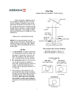
Page 5: ...d Shell Exhaust Outlet Roof Jack Internal Ventilator Use proper size round ducting 600 CFM requires 8 50 sq in 1200 CFM requires 10 78 sq in 1 Top View Duct Positioning Wall Side Duct Location Wall Side Wall Hood stack against wall Wall Hood stack centered Luna Quantum models Duct Location Duct Location Island Hood Duct Centered Duct Centered Backdraft Damper Duct Stub From Ceiling Proper ductwork...

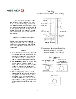
Page 6: ...st Outlet Internal Ventilator Wall Louver Duct Stub From Wall Use proper size round ducting 600 CFM requires 8 50 sq in 1200 CFM requires 10 78 sq in 1 Top View Duct Positioning Wall Side Duct Location Wall Side Wall hoods with stack against wall Wall hoods with stack centered Luna and Quantum models Duct Location Duct Location Island Hoods Duct centered front to rear Backdraft Damper Proper ductw...

Page 7: ...motor s 5 Unscrew blower plate s from ceiling of liner and set mounted blower plate s aside 6 Feed conduit from service panel into knock out labeled Power Supply and secure with appropriate connector 7 Lift liner up into hood reaching up through exhaust outlet to transition top guide liner into place Re secure liner to hood body using 8 x Phillips head sheet metal screws 8 Lift Light Only Panel up...

Page 8: ...backing previously installed in wall behind hood 6 Drill mount holes through solid back wall of hood cabinet use cobalt drill bit on stainless hoods 2 up from base of hood on center with at least two studs Drill upper attachment hole as close to hood centerline and as high up from hood bottom as possible 7 Lift hood into position and secure firmly to wall studs or backing with lag bolts and lock n...

Page 9: ...ack in position to hanging frame with sheet rock screws Firmly attach stack to hanging frame with bolts lock washers and nuts If running duct work through joist bay cut away the side above the ceiling line that will allow an adjustable elbow to turn into the bay 6 If overall height of hood would position the bottom below recommended clearance above cooking surface excess stack may be cut off NOTE ...

Page 10: ...hite and green to green 11 Secure Light Switch Control Panel to liner wall with screws provided 12 Tape joint between transition top to round ductwork from inside running strips of metal foil tape vertically 13 Reattach blowers to liner ceiling and re plug blower harness es SYSTEM TESTING 1 Turn on electrical circuit to hood 2 Switch on ventilator Rotate variable speed control knob clockwise throu...

Page 11: ...ontal direction DO NOT USE A CIRCULAR MOTION Use a NON ABRASIVE POLISH ABBAKA makes no specific product endorsements However products such as WENOL SIMICHROME and FLITZ have been found effective 3 Normal body oils are in part alkali in composition Consequently fingerprints will turn to tarnish on cop per or brass After polishing a light application of wax will retard tarnishing The wax creates a p...

Page 12: ...ers with abra sives as they may scratch the enamel or stainless steel Brass utensil rails if included may be cleaned with a copper or brass polish see previous page Polished stainless steel rails may be cleaned with a soft cloth dampened with a mild soap and water solution then buffed with a dry clean cloth to restore its luster NOTE Always clean and polish with the grain of the hood The grain is ...

Reviews: