background image

TM402-200 OPERATOR’S MANUAL

SYMPTOM

CAUSE

CORRECTIVE ACTION

Motor will not start.

1. Low Voltage.
2. Open circuit in motor or loose 
connections.
3. Blown fuse or breaker.
4. Not plugged in or switched on 
at wall

1. Check power source for proper voltage.
2. Inspect all lead connection on motor for loose or open 
connections. (Send for Servicing.)
3. Short circuit. (Send for Servicing.)
4. Improper match between tool and circuit, fuse or breaker.

Motor will not start –
fuses or circuit
breakers tripping or
blowing.

1. Short circuit in line, cord or plug.
2. Short circuit in motor or loose 
connections.
3. Incorrect fuses or circuit breakers 
in power line

1. Inspect cord or plug for damaged insulation and shorted wires.
2. Inspect all connections on motor for loose or shorted terminals 
and/or worn insulation.
3. Install correct fuses or circuit breakers or
switch tool to an appropriately sized circuit.

Motor overheats.

1. Motor overloaded.
2. Extension cord too long and 

insufficient gauge (weight).

1. Reduce load on motor.
2. Utilize an extension cord of appropriate gauge and length or plug 
tool directly into outlet.

Motor stalls (resulting
in blown fuses or
tripped circuit).

1. Short circuit in motor or loose 
connections.
2. Low voltage.
3. Incorrect fuses or circuit breakers 
in power line.
4. Motor overload.

1. Inspect connections on motor for loose or shorted terminals or 
worn insulation. (Send for Servicing.)
2. Correct low voltage conditions (for example: improper extension 
cord length and/or gauge).
3. Install correct fuses or circuit breakers or plug tool into an 
appropriate circuit, matched to an appropriate fuse or breaker.
4. Reduce the load on the motor.

Machine slows when
operating.

1. Feed rate too great.

1. Reduce the rate at which the workpiece is fed into the working 
area of the tool

Wavy condition on
surface of workpiece

1. Machine vibrating.

2. Workpiece is not being held firmly

3. Wheel face uneven.
4. Wheel is too hard.

1. Ensure machine is securely mounted on a solid surface.

2. Use a holding device to firmly retain the workpiece.

3. Dress the grinding wheel.
4. Use softer wheel, or reduce the feed rate.

Lines on surface of
workpiece.

1. Impurity on surface of wheel.
2. Workpiece not being held tightly

1. Dress the grinding wheel.

2. Try holding the device to more firmly retain 

Burning spots or
cracks in the
workpiece.

1. Improper type of grinding wheel.
2. Improper feed rate.

1. Try wheels with softer bond or coarser grit.
2. Slow down the rate at which the workpiece is fed into the wheel.

Wheel dulls quickly, grit 
falls off

1. Feed rate is too aggressive.
2. Wheel is soft.
3. Wheel diameter too small.
4. Bad wheel dressing.
5. Defective wheel bonding.

1. Decrease feed rate of workpiece into grinding wheel.
2. Select a grinding wheel with a harder bond of material.
3. Replace wheel.
4. Dress the wheel.
5. DO NOT USE – return wheel to point of purchase

Wheel clogs and
workpiece shows
burn marks.

1. Wheel is too hard.
2. Feed rate is too slow.
3. Bad wheel dressing.

1. Select a grinding wheel with a softer bond of material.
2. Increase the feed rate of the workpiece into the grinding wheel.
3. Dress the wheel.

TROUBLESHOOTING

10

www.itmtools.com.au

Summary of Contents for TM402-200

Page 1: ...www itmtools com au Ver 1 2 TM402 200 OPERATOR S MANUAL BUFFING MACHINE INDUSTRIAL 200MM ...

Page 2: ...pair agent which shall be the buyer s sole and exclusive remedy for defective goods ITMS accepts no additional liability pursuant to this guarantee for the costs of travelling or transportation of the product or parts to and from ITMS or the service agent or dealer such costs are not included in this warranty Our goods come with guarantees which cannot be excluded under the Australian Consumer Law...

Page 3: ...ts Arsenic and chromium from chemically treated lumber Users of these tools should review the chemical composition of the work surface and any products in conjunction with the operation of these tools for any such chemicals prior to engaging in any activity that creates dust and or microscopic particles Users should obtain the material safety data sheets from all identified chemicals either from t...

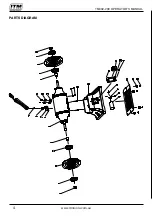
Page 4: ...TM402 200 OPERATOR S MANUAL PARTS DIAGRAM 4 www itmtools com au ...

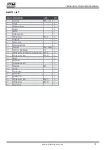
Page 5: ... 9 Power cord 1 10 Strain relief plate 1 11 Hex bolt M16 Right 1 12 Tooth Locked Washer D4 1 13 Philips screw with flat and spring washer M4 8 2 14 Philips screw assy M6 20 2 15 Base 1 16 Capacitor 1 17 Capacitor support 1 18 Hex bolt M8 1 19 Switch 1 20 Switch plate 1 21 Base plate 1 22 Rubber foot 4 23 Philips screw assy M4 12 4 24 Philips screw M4 16 2 25 Strain relief 1 5 www itmtools com au ...

Page 6: ...ool Keep cord away from heat oil sharp edges or moving parts Damaged or entangled cords increase the risk of electric shock e When operating a power tool outdoors use an extension cord suitable for outdoor use Use of a cord suitable for outdoor use reduces the risk of electric shock Personal Safety a Stay alert watch what you are doing and use common sense when operating a power tool Do not use a ...

Page 7: ...AFETY RULES FOR BENCH GRINDERS a Ensure that the bench grinder is disconnected from the mains supply when not in use before servicing or making adjustments and when changing accessories such as grinding wheels b Always use the correct type of grinding wheel for the type of operation to be carried out and the material being machined Do not use a grinding wheel as a cutting disc c Only use grinding ...

Page 8: ...nch grinder should only be performed by an authorized qualified technician WARNING Ensure the bench grinder is disconnected from the power supply when performing maintenance tasks to avoid injury n Keep guards in place and in good working order With the machine disconnected from the mains supply check that the guards are secure and fitted correctly o Always keep the tool rest as close to the grind...

Page 9: ...djust to the correct position The gap between the tool rest and grinding wheel should be set to 2mm Bench Mounting The Grinder can be secured with screws or nuts and bolts Locate the mounting holes The length of the bolts or screws will depend on the thickness of the bench Where a steel bench is used it is best to mount the grinder on to a board then attach the board to the bench this will also mi...

Page 10: ...ength and or gauge 3 Install correct fuses or circuit breakers or plug tool into an appropriate circuit matched to an appropriate fuse or breaker 4 Reduce the load on the motor Machine slows when operating 1 Feed rate too great 1 Reduce the rate at which the workpiece is fed into the working area of the tool Wavy condition on surface of workpiece 1 Machine vibrating 2 Workpiece is not being held f...

Reviews: