


Abbott & Ashby Linisher Installation Manual
15
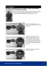
MOUNTING:
The grinder can be secured with screws or nuts and bolts to a workbench or pedestal
stand. The length of the fasteners will depend on the thickness of the work surface. Where
a steel bench is used it is best to mount the grinder to a board, then attach the board to the
bench as this will also minimise vibration.
SWITCHING ON AND OFF:
Before connecting to the power supply rotate the wheel by hand to ensure that it is running
free from obstruction. Connect to the mains supply and press the rocker switch to the ON
position (l). To stop the machine simply press the rocker switch to the OFF position (O).
We also recommend the use of the E-Stop switch ATPED-ESTOP (sold separately)
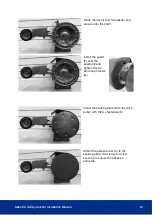
REPLACING GRINDING WHEEL:
Remove guard by untightening 3 x 6 x 10mm cap screws. Remove 16mm nut and replace
wheel. Choose the correct grit to suit your application. Hand spin the wheel to ensure it
spins freely and true. Reinstall guards.
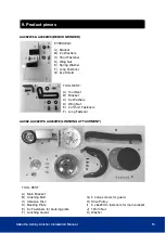
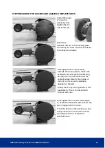
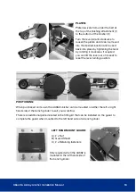
WORKING ANGLE ADJUSTMENT:
Loosen the bolt (A) out of the locking position and lift latch
(B) to disengage the locking teeth (C); rotate the linisher to
the desired angle. Lock the latch back into place firmly into
the locking teeth and fasten the bolt to secure the linisher
into position.
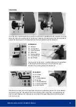
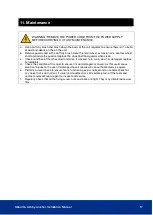
GUARD:
Designed for user ease when changing belts or servicing the
unit. No need to remove other components in order to
remove the guard. Loosen 3 x cap screw (A), rotate the guard
slightly and remove.
A
B
C
A
A
A


