CONFIG
SOFTW
ARE
UPDA
TE
CHASSIS
ADDRESS
525/
AUTO
/625
RJ1
1
C
DEBUG
MASTER
RESET
1
2
3
5
6
7
8
4
ON
45
6789ABC
DEF01
23
CPU HALT
SCSI GRT
SCSI BSY
ENET REC
ENET TRA
ENET ACK
AN REF
601
RS 485Rx
RS 485Tx
MRx 232
MTx 232
Rx LINC
Tx LINC
RRx 232
RTx 232
Rx DEBUG
Tx DEBUG
Rx SMPTE
Tx SMPTE
DISK 2
DISK 1
5V
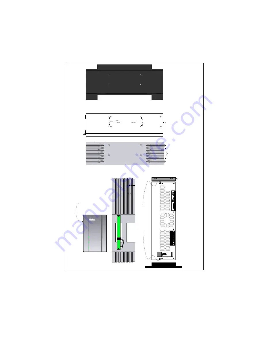
The main
front cover
snaps onto
these front
panel
mounting
posts.
Top/Bottom
Panel
Mounting
Holes
Make sure these
front panel
alignment tabs
are at the front
of the main
chassis.
Use the included M4 X 14 (metric)
Phillips head screws to attach the
top cover and base.
This cover snaps
over the main
front cover.
D I S K U S
Digital
Disk
Recorder
Main Front Cover
Main Chassis
Front View
Tower Base
Place the end
of the chassis
with the power
switch onto the
base.
Main Chassis Top/Bottom View
Top Cover
Base
Top Cover
(end view)
Tower Configuration
Diskus Technical Guide
Assembling the Main Chassis
9100-0217-02 - SEP 95
Installation
7-11
Summary of Contents for Diskus
Page 1: ...Diskus Digital Disk Recorder Manual ...
Page 477: ...NOTES Diskus Operations Index 9100 0217 02 SEP 95 Index xvii ...
Page 478: ...NOTES Index Diskus Operations xviii Index 9100 0217 02 SEP 95 ...
Page 479: ...NOTES Diskus Operations Index 9100 0217 02 SEP 95 Index xix ...
Page 480: ...NOTES Index Diskus Operations xx Index 9100 0217 02 SEP 95 ...


