Controlling Multiple Diskus Chassis
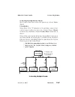
One Control Panel can select and operate up to four Diskus
chassis.
Installation
Using three 9 Pin "Y" adapters (or by splicing), connect four
control panel cables between the Control Panel Chassis
connector and the Diskus chassis Control Panel connectors as
shown.
Three of the control panel cables must be modified to not power
the Control Panel, by opening pin 1 (+12VDC), at the chassis (15
Pin) end. Use the unmodified cable at a chassis near the Control
Panel, to power the Control Panel.
NOTE: If the unmodified cable is over 150 feet, you
must power the Control Panel using an external
power supply.
Diskus 1
Diskus 2
Diskus 3
Diskus 4
Control
Panel
Chassis
Control
Panel
Control
Panel
Control
Panel
Control Panel
Chassis Address 1
Chassis Address 1
Keyboard Address 5
Chassis Address 2
Chassis Address 3
Chassis Address 4
Ext
Ref
15 Pin
Pin 1 open
15 Pin
Pin 1 open
15 Pin
Pin 1 open
15 Pin
9 Pin
9 Pin
9 Pin
9 Pin
9 Pin
Data and
Control Panel
Power
Data
only
Data
only
Data
only
3 "Y" Splitters used
All 9 Pin connections
are in parallel.
T
Connecting Multiple Chassis
Diskus Technical Guide
Connecting Diskus
9100-0217-02 - SEP 95
Installation
7-27
Summary of Contents for Diskus
Page 1: ...Diskus Digital Disk Recorder Manual ...
Page 477: ...NOTES Diskus Operations Index 9100 0217 02 SEP 95 Index xvii ...
Page 478: ...NOTES Index Diskus Operations xviii Index 9100 0217 02 SEP 95 ...
Page 479: ...NOTES Diskus Operations Index 9100 0217 02 SEP 95 Index xix ...
Page 480: ...NOTES Index Diskus Operations xx Index 9100 0217 02 SEP 95 ...


