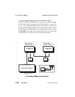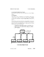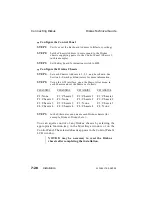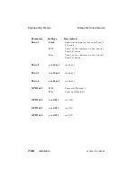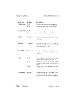
Configure the Control Panel
STEP 1:
Verify or set the Keyboard Address to 5 (factory setting).
STEP 2:
Set the Chassis Address to correspond to the Diskus
chassis supplying power to the Control Panel (Chassis 1,
in this example).
STEP 3:
Set the Keyboard Termination switch to Off.
Configure the Diskus Chassis
STEP 1:
Set each Chassis Address to 1, 2, 3, and 4 as shown. See
Section 8 - Switches & Indicators for more information.
STEP 2:
Using the GUI interface, open the Macro Alias menu in
each chassis and set the Macros as follows:
CHASSIS 1
CHASSIS 2
CHASSIS 3
CHASSIS 4
F1 : None
F1 : Chassis 1
F1 : Chassis 1
F1 : Chassis 1
F2 : Chassis 2
F2 : None
F2 : Chassis 2
F2 : Chassis 2
F3 : Chassis 3
F3 : Chassis 3
F3 : None
F3 : Chassis 3
F4 : Chassis 4
F4 : Chassis 4
F4 : Chassis 4
F4 : None
STEP 3:
In the Ethernet menus, name each Diskus chassis (for
example, Diskus1, Diskus2, etc.).
You can aquire control of any Diskus chassis by selecting the
appropriate function key, in the Misc Keys window or on the
Control Panel. The selected chassis appears in the Control Panel’s
LCD window.
NOTE: It may be necessary to reset the Diskus
chassis after completing the installation.
Connecting Diskus
Diskus Technical Guide
7-28
Installation
9100-0217-02 - SEP 95
Summary of Contents for Diskus
Page 1: ...Diskus Digital Disk Recorder Manual ...
Page 477: ...NOTES Diskus Operations Index 9100 0217 02 SEP 95 Index xvii ...
Page 478: ...NOTES Index Diskus Operations xviii Index 9100 0217 02 SEP 95 ...
Page 479: ...NOTES Diskus Operations Index 9100 0217 02 SEP 95 Index xix ...
Page 480: ...NOTES Index Diskus Operations xx Index 9100 0217 02 SEP 95 ...


