Section 9
Switches & Indicators
Overview
This section discusses the Diskus switches used to alter various
parameters prior to installation, and the indicators that show
Diskus’ current status.
Both the switches and indicators are fitted to the front edge of the
Diskus main circuit board. You can access them by removing the
front panel, which is held in place by a spring clip on either side.
Remove the front panel by simply pulling it straight off.
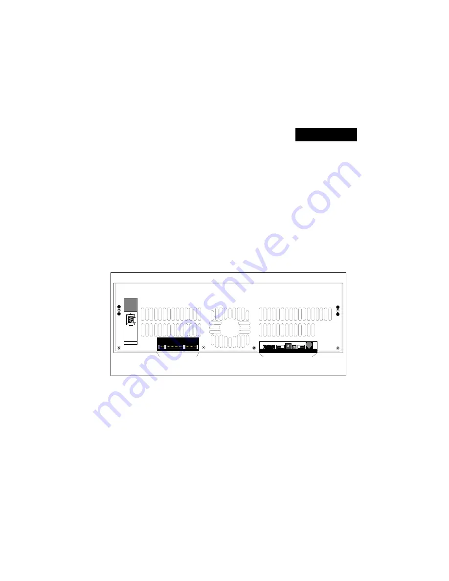
After removing the front panel, you will see a row of switches to
the right of the fan and a row of indicators to the left of the fan,
as shown above.
CONFIG
SOFTWARE
UPDATE
CHASSIS
ADDRESS
525/
AUTO/625
RJ11C
DEBUG
MASTER
RESET
1 2 3
5 6 7 8
4
ON
456
9
012
3
CPU HAL
T
SCSI GRT
SCSI BSY
ENET
REC
ENET
TRA
ENET
ACK
AN REF
601
RS 485Rx
RS 485Tx
MRx 232
MTx 232
Rx LINC
Tx LINC
RRx 232
RTx
232
Rx DEBUG
Tx DEBUG
Rx SMPTE
Tx SMPTE
DISK 2
DISK 1
5V
LED INDICATORS
CONFIGURATION AND
SETUP SWITCHES
Switches and Indicators on Diskus Front Panel
Diskus Technical Guide
Overview
9100-0217-02 - SEP 95
Switchers & Indicators
9-1
Summary of Contents for Diskus
Page 1: ...Diskus Digital Disk Recorder Manual ...
Page 477: ...NOTES Diskus Operations Index 9100 0217 02 SEP 95 Index xvii ...
Page 478: ...NOTES Index Diskus Operations xviii Index 9100 0217 02 SEP 95 ...
Page 479: ...NOTES Diskus Operations Index 9100 0217 02 SEP 95 Index xix ...
Page 480: ...NOTES Index Diskus Operations xx Index 9100 0217 02 SEP 95 ...


