Section 10
Connectors
Overview
This section outlines Diskus connectors and the signals present
on the connectors. Carefully examining the connector pinouts
before constructing cables will considerably simplify the
installation process.
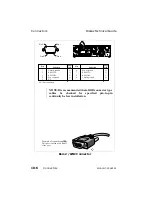
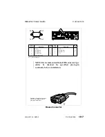
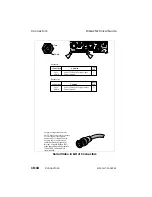
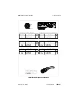
Each connector is shown as viewed from the outside of the
chassis. Each connector includes a table that defines the signals
present on each pin and whether the signal is an input or an
output signal.
On the front of the chassis is a connector marked "debug." This
connector is used during the manufacturing process and is not
used in normal Diskus operations.
NOTE: It is recommended that all DB connector type
cables be checked for specified pin-to-pin
continuity before installation.
Diskus Technical Guide
Overview
9100-0217-02 - SEP 95
Connectors
10-1
Summary of Contents for Diskus
Page 1: ...Diskus Digital Disk Recorder Manual ...
Page 477: ...NOTES Diskus Operations Index 9100 0217 02 SEP 95 Index xvii ...
Page 478: ...NOTES Index Diskus Operations xviii Index 9100 0217 02 SEP 95 ...
Page 479: ...NOTES Diskus Operations Index 9100 0217 02 SEP 95 Index xix ...
Page 480: ...NOTES Index Diskus Operations xx Index 9100 0217 02 SEP 95 ...


