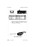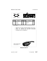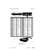
NOTE: It is recommended that all DB connector type
cables be checked for specified pin-to-pin
continuity before installation.
O
-
I
-
I
-
-
-
Chassis ground
I/P or
O/P
Function
O
Power ground
RS422 Rx +A
RS422 Tx +A
RS422 Tx -A
Power ground
N.C.
1
Chassis ground
RS422 Rx -A
N.C.: Not connected
Pin
number
Function
Pin 1
Pin 6
Pin 5
Pin 9
Pin
number
I/P or
O/P
2
3
4
5
6
7
8
9
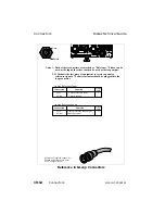
Example of required connector.
This is connected as an RS422 slave port.
11
5
230
PUSH
115/230V~1/0.5A
SERIAL O/P
OPTION
REF
SERIAL I/P
SCSI
LTC IN
LTC OUT
MOUSE
RS232 / GPI
CONTROL PANEL
REM 1 IN / OUT
REM 2 / LINC
ETHERNET
DISK
G
B
R
Y
U
V
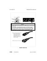
DISCONNECT MAINS BEFORE SERVICING
NO USER SERVICABLE PARTS INSIDE.
HARMFUL INTERFERANCE, AND (2) THIS DEVICE
MUST ACCEPT ANY INTERFERANCE RECIEVED
THIS DEVICE COMPLIES WITH PART 15 OF FCC
RULES FOR CLASS A. COMPUTING EQUIPMENT
OPERATION IS SUBJECT TO THE
FOLLOWING
CONDITIONS. (1) THIS DEVICE MAY NOT CAUSE
INCLUDING INTERFERENCE
THAT
MAY CAUSE
UNDESIRED OPERATION.
A.C. OUTPUT. 100 / 240 VAC, 1 / 0.5 AMPS
100 / 240 VAC, 50 / 60 Hz,
3.0 / 1.5 AMPS MAX.
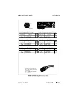
Rem 1 In/Out Connector
Diskus Technical Guide
Connectors
9100-0217-02 - SEP 95
Connectors
10-5
Summary of Contents for Diskus
Page 1: ...Diskus Digital Disk Recorder Manual ...
Page 477: ...NOTES Diskus Operations Index 9100 0217 02 SEP 95 Index xvii ...
Page 478: ...NOTES Index Diskus Operations xviii Index 9100 0217 02 SEP 95 ...
Page 479: ...NOTES Diskus Operations Index 9100 0217 02 SEP 95 Index xix ...
Page 480: ...NOTES Index Diskus Operations xx Index 9100 0217 02 SEP 95 ...


