A
B
A
B
Note: The rail can be mounted with inlet at top or bottom position.
Note: The flow control should be inserted with the protruding side into the
showerhead, taking care not to cause and damage to the flow controller. In
accordance with AS/NZS3662 CI.6e. These showers may not be suitable for
use with gravity fed waterheaters, low and unequal pressure supply networks,
instantaneous water heaters, tempering valves and/or thermostatic mixing
valves. In accordance with AS/NZS3662CI.6c.
The following pressure range should be complied with:
·Minimum working pressure 150Kpa
·Maximum working pressure 750Kpa
ALL ABEY SHOWERS MUST BE INSTALLED IN ACCORDANCE WITH
AS/NZS3500 SERIES.
ALL ABEY SHOWERS ARE CERTIFIED IN ACCORDANCE WITH
AS/NZS 3662:2005, LICENCE NUMBER WM-022172.
Measure the Dimension “
X
” between the centres of wall bases.
1.
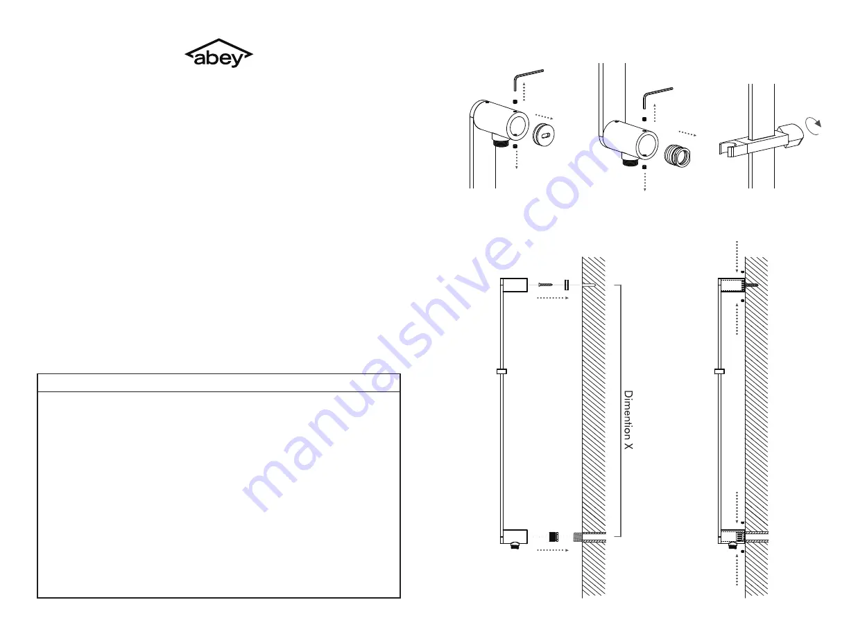
Loosen the grub screws and remove the top insert
(A)
from rail. Position the
insert on the wall. The distance between the threaded insert
(B)
centre and the
top insert
(A)
centres should be dimention “
X
”.
2.
Loosen the grub screws and remove the threaded insert
(B)
from rail. Screw
the thread inset
(B)
fitting onto lugged elbow (protruding from the wall).
3.
Drill a diameter 6mm holes and attach top insert
(A)
with raw-plugs and screws
provided.
4.
Insert the rail onto the threaded insert
(B)
and top insert
(A)
simultaneously.
Then tighten grub screws.
5.
Attach the hose to the hand shower and the outlet on the rail.
6.
The hand shower holder is movable when you loosen the handle.
7.
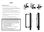
Installation Guide


