background image

Contact Information

Customer Support

For additional information on the use or setup of the Ground Drive Broadcast Spreader, please 
contact the ABI customer support team at 855.211.0598.

Additional support videos

 are available at the ABI support page ( abisupport.com ) under each tool.

Warranty Information and Return Policy

 - Warranty and return policy information can also be

found on the ABI support page under each tool. For additional questions regarding warranty or
return policy, contact the ABI customer support team at 855.211.0598.

ABI Attachments, Inc
520 S. Byrkit Ave.
Mishawaka, IN 46544

Email: support@abiattachments.com
Phone: 877-788-7253
Website: www.abisupport.com

To order parts or to speak to one of ABI’s Customer Service 
Representatives contact us Monday to Friday 9am to 5pm EST.

Summary of Contents for ABI-BS-GD-339

Page 1: ...s Manual Broadcast Spreader Form No 10 80086 Rev 1 10 11 2021 NOTE This Owner s Manual covers several models Features may vary by model Not all features in this manual are applicable to all models and the model depicted may differ from yours ...

Page 2: ...or need product support NOTE This operators manual covers several models Features may vary by model Not all features in this manual are applicable to all models depicted may differ from yours Model Number Serial Number Version Number Purchaser s Name ABI Attachments Inc 520 S Byrkit Ave Mishawaka IN 46544 Email abicustomerservice abiattachments com Phone 877 788 7253 Website www abisupport com Tab...

Page 3: ... part to ABI or independent service technician within 30 days of defect discovery or failure for return inspection or repair if required If ABI is unable to repair the product to conform to the warranty in a reasonable number of attempts ABI will provide at its option one of the following a a replacement for the product or b a full refund of the purchase price Repair replacement or refunds are the...

Page 4: ... Operate tow vehicle and controls from the driver s seat only Never dismount from a moving tow vehicle or leave tow vehicle unattended with engine running Do not allow anyone to stand between tow vehicle and implement while backing up to implement Keep hands feet and clothing away from power driven parts While transporting and operating equipment watch out for objects overhead and along side such ...

Page 5: ...on the uphill side Understand procedure before doing work Refer to the Operator s Manual for additional information Work on a level surface in a clean dry area that is well lit Lower implement to the ground and follow all shutdown procedures before leaving the operator s seat to perform maintenance Do not work under any hydraulic supported equipment It can settle suddenly leak down or be lowered a...

Page 6: ... to help protect against serious injury or death from falling and machine overturn Never carry riders on tractor or implement Riders obstruct operator s view and interfere with the control of the tow vehicle Riders can be struck by objects or thrown from the equipment Never use tractor or implement to lift or transport riders Wear protective clothing and equipment appropriate for the job such as s...

Page 7: ...Call Toll Free 877 788 7253 Email support abiattachments com 7 Safety Labels ...

Page 8: ... skid and set them in an area where all parts can be viewed Fig 3 3 Cut open main support frame towing hitch package and remove zipties then set parts off to the side Fig 4 5 4 Open white bag of components and set them in an area where all parts can be viewed Fig 6 and 7 5 Open plastic bag of hardware from the white bag and set in an area where all parts can be viewed Fig 8 6 Set all hopper compon...

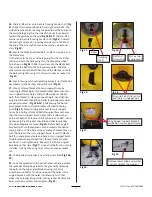
Page 9: ...rench while keeping the mobile shutter facing the direction as the hole in the side of the hopper Fig 3 4 Then set aside 3 Locate curved guard Main support frame 2 M8x20 bolts 2 Ø8 flat washers and 2 M8 nuts Fig 5 4 Fasten the curved guard onto the frame using the M8x20 bolts Ø8 washers and M8 nuts hand tighten only at this time Fig 6 5 Locate spreader disc main support frame flat cotter pin and h...

Page 10: ... stirrer guard 2 M8x20 carriage bolts 2 fender washers 2 lockwashers and 2 M8 nuts Fig 15 10 Looking inside the hopper place the stirrer guard over the stirrer and align the slots on the stirrer guard over the two holes in the hopper wall on either side of the stirrer Fig 16 Insert the 2 M8x20 carriage bolts thru the slots on the stirrer guard then thru the holes in the hopper wall and on thru the...

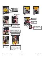
Page 11: ...main support frame by inserting 2 M8x40 bolts thru pivot bracket holes then thru main support frame holes Slide 1 Ø8 washer onto both bolts then thread 1 M8 nut onto each bolt hand tighten only Pivot bracket should be parallel to spreader disc when properly mounted Fig 33 34 Slide towing hitch onto pivot bracket with 2nd pivot bracket attached to towing hitch Fig 35 Mount 2nd pivot bracket to main...

Page 12: ...d guard to main support frame from Fig 6 once flow control bracket hole is centered in slot on curved guard Re thread the flow control adjustment knob and washer thru the curved guard slot and into the threaded hole on the flow control assembly bracket Fig 21 Fig 20 Slide flat plate on flow control assembly into grooves on mobile shutter attached to the bottom of the hopper Rotate curved guard up ...

Page 13: ... Mount 2nd pivot bracket to main support frame Rotate angled brackets with multiple holes until hole at the end of the angled brackets line up with holes in the main support frame Angled brackets mounted to towing hitch Pivot bracket should be parallel to spreader disc when properly mounted Mount 1st pivot bracket to main support frame Spreader disc Slide towing hitch onto pivot bracket with 2nd p...

Page 14: ...ting the amount of material to be spread C Regulating the spreading width To regulate the A spread pattern loosen the knob Fig 25 in front of the curved guard Fig 5 6 Slide to the left or right the flow control assembly mentioned in Fig 20 21 which is located under the hopper and runs through the slot in the curved guard This moves the spread pattern from 180 at position 0 in the center to either ...

Page 15: ... do not fit properly can slip and cause injury 2 Right hand and left hand sides of the implement are determined by facing in the direction the implement will travel when going forward 3 The broadcast spreader should be used to distribute granular fertilizers seeds sand and small granular salt It is not designed for use with powder type material 4 The broadcast spreader ground driven fertilizer spr...

Page 16: ...Visit www abisupport com 16 Parts Description 103 230 106 230 Broadcast Spreader Assembly Fig 44 ...

Page 17: ...Call Toll Free 877 788 7253 Email support abiattachments com 17 ...

Page 18: ...f corrosive material has eaten under the paint clean off the area with a wire brush and touchup with primer and paint C Tighten all hardware D Apply a thick layer of grease to all exposed moving parts E Apply a film of biodegradable oil in crevasses and corners F Cover the spreader from the elements in order to have it in perfect condition for the start of the next season 5 The gearbox has been fi...

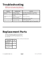
Page 19: ... OR SHEARED BROKEN RING OR PINION GEAR REPLACE BOLT REPLACE COTTER PIN REPLACE RING OR PINION GEAR NARROW SPREAD WIDTH SLOW GROUND SPEED HOPPER TOO FAR BACKWARDS INCREASE GROUND SPEED POSITION SPREADER SO IT RUNS LEVEL OR INCLINED SLIGHTLY FORWARD TOWARD THE TOWING VEHICLE Replacement Parts All of the Classic Spreader components are considered wear parts and will need to be replaced as they wear o...

Page 20: ...ormation and Return Policy Warranty and return policy information can also be found on the ABI support page under each tool For additional questions regarding warranty or return policy contact the ABI customer support team at 855 211 0598 ABI Attachments Inc 520 S Byrkit Ave Mishawaka IN 46544 Email support abiattachments com Phone 877 788 7253 Website www abisupport com To order parts or to speak...

Reviews: