The lower hitch pins
(see fig. 3)
may be put in either of 2 positions (upper or lower)
depending on the tractor. Secure the two arms with the lynch pins. Tighten the tractor
arms side movement with either the sway chains or blocks to limit side swing to 2”-3”.
Connect the top link, locking it in place with the top hitch pin. Adjust it so the Command
Seeder is as near parallel to the ground as possible. A 1° to 2° rearward tilt is
acceptable
(see fig. 4)
.
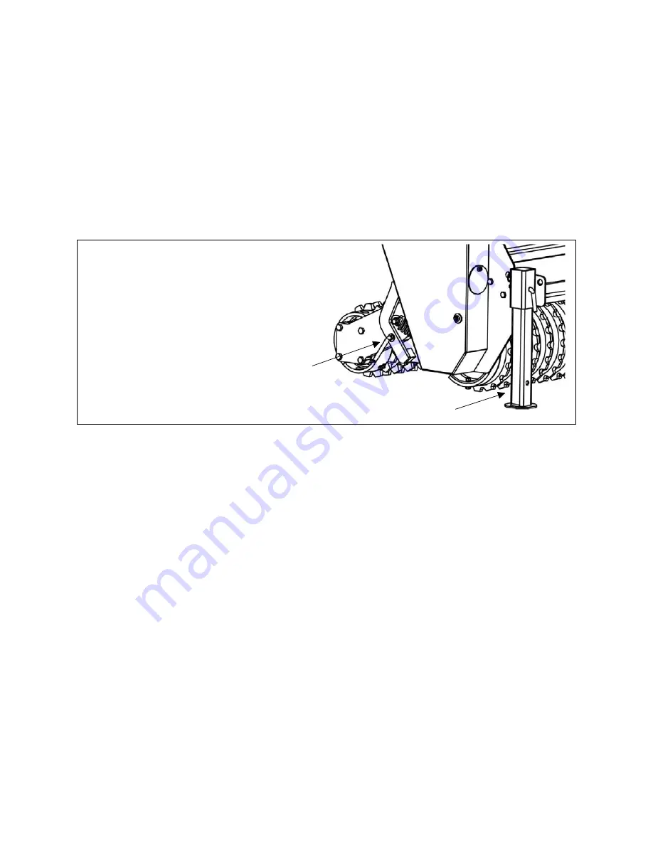
After use, the machine should be lowered and allowed to rest on the stand, and the rear
cultipacker should be blocked by inserting the two locking pins secured with hairpin
cotters
(see fig. 5)
.
3.04 - General Instructions for Use
After you have read the Operator’s Manual, have gone through the Pre-Operational
Checklist and have correctly connected the Command Seeder to the three-point hitch of
the tractor, simply fill the hopper with seed, adjust the required calibration and
distribution and you are ready to begin work.
Seed distribution is achieved from the forward motion of the tractor. As the front
cultipacker of the Command Seeder moves forward, the movement of the front
cultipacker is transmitted by chains through a series of gears, to the seed cups which
control the release of seed from the hopper. This allows for the seed to be sown
constantly and in proportion to the distance covered by the tractor without being
affected by its speed.
If the area to be seeded has already been tilled, then the front cultipacker will level the
soil to provide a better seed bed. If, on the other hand, the land has not been prepared
in any way, the cultipacker will break up the crust, splitting the largest clods, burying the
smaller stones and basically preparing a no-till seed bed.
The seed is distributed with precision and in a predetermined manner in the area
between the two rotors. The rear cultipacker then incorporates the seed into the soil to
improve germination.
Avoid seeding when it is raining or when the soil is too wet.
O
PERATION
13
ABI A
TTACHMENTS
C
OMMAND
S
EEDER
O
PERATOR
’
S
M
ANUAL
1
2
Fig. 5
1. stand
2. locking pin


