background image

Visit: 

www.abisupport.com

20

Brake Controller Adjustments

Brake Shoe Manual Adjustments

A NOTE: The electronic braking system is not 

compatible with ALL tow vehicles. Please contact 

ABI for more information: 877-788-7253 or log on to 

ABIsupport.com.

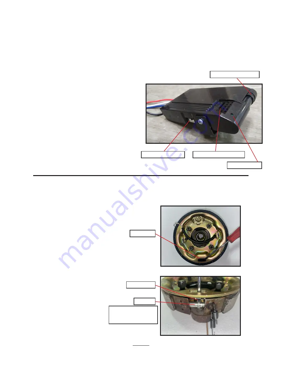
ABI offers power brakes as a standard feature on the dual 

axle Workman XL only. Mounted within the black 

box on the Workman XL Trailer is a Brake Controller, which 

allows adjustment to the time delay and power intensity 

of the trailer brakes.
First, make sure power is being supplied to the brake 

controller by hooking up the 4-pole wire connection to 

the ATV and turning on the ATV ignition. 

NOTE:

 Be sure to 

have a strong, well charged battery for full braking power. 

Squeeze the Manual Brake Activator and note that red 

lights appear by the Power Intensity Adjuster. The more 

lights that activate, the more stopping power applied to 

the Workman XL trailer brakes.

More Stopping Power:

 Move the Power Intensity Adjuster 

to the Left, towards the (+) positive symbol.

Less Stopping Power:

 Move the adjuster to the Right 

towards the (-) negative symbol.

After using your trailer for some time, you may need to 

manually adjust the brake shoes located within the brake 

drum. At the bottom, inside portion of each brake hub 

you will note an elongated plastic cap. Remove this cap as 

indicated (

Fig 61

).

Inside the hole of the hub, you will note a silver adjuster. 

Insert a brake spoon or a screwdriver into the hole, and 

spin the teeth down to expand or add more stopping 

power to each hub (

Fig 62

). Spin the teeth up to contract 

or decrease the brake pads from contacting the brake 

drum. The direction ‘down’ would be to spin the circular 

adjuster in a direction towards you. Imagine the adjuster 

to be like a coin rolling on a table towards you, that is the 

direction of ‘down’.

The brake hub in these views has been removed from the 

axle for illustrative putposes only.

The Time Delay Adjuster allows to place a 1-3 second delay 

when applying the trailer brakes. Check that the switch is 

pushed to the back, in the opposite direction of the power 

on Light, for instant stopping power. The factory default is 

set to instant stopping or no delay.

Manual Brake Activator.

Power Intensity Adjuster.

Time Delay Adjuster.

Pastic Cap.

Screwdriver.

Adjuster.

Spin the teeth on the 

Adjuster down for more 

stopping power.

Power On Light.

Fig 61.

Fig 62.

Summary of Contents for Workman XL

Page 1: ...al Workman XL Form No 10 80077 Rev 3 7 6 2021 NOTE This Owner s Manual covers several models Features may vary by model Not all features in this manual are applicable to all models and the model depicted may differ from yours ...

Page 2: ...s manual covers several models Features may vary by model Not all features in this manual are applicable to all models depicted may differ from yours Model Number Serial Number Invoice Number Purchaser s Name ABI Attachments Inc 520 S Byrkit Ave Mishawaka IN 46544 Email abicustomerservice abiattachments com Phone 877 788 7253 Website www abisupport com Table of Contents Warranty 3 Safety 4 SafetyL...

Page 3: ...ndent service technician within 30 days of defect discovery or failure for return inspection or repair if required If ABI is unable to repair the product to conform to the warranty in a reasonable number of attempts ABI will provide at its option one of the following a a replacement for the product or b a full refund of the purchase price Repair replacement or refunds are the warranty holder s EXC...

Page 4: ...ate tow vehicle and controls from the driver s seat only Never dismount from a moving tow vehicle or leave tow vehicle unattended with engine running Do not allow anyone to stand between tow vehicle and implement while backing up to implement Keep hands feet and clothing away from power driven parts While transporting and operating equipment watch out for objects overhead and along side such as fe...

Page 5: ...on the uphill side Understand procedure before doing work Refer to the Operator s Manual for additional information Work on a level surface in a clean dry area that is well lit Lower implement to the ground and follow all shutdown procedures before leaving the operator s seat to perform maintenance Do not work under any hydraulic supported equipment It can settle suddenly leak down or be lowered a...

Page 6: ... to help protect against serious injury or death from falling and machine overturn Never carry riders on tractor or implement Riders obstruct operator s view and interfere with the control of the tow vehicle Riders can be struck by objects or thrown from the equipment Never use tractor or implement to lift or transport riders Wear protective clothing and equipment appropriate for the job such as s...

Page 7: ...Call Toll Free 877 788 7253 Email support abiattachments com 7 Safety Labels are we actually adding this label to the trailer ...

Page 8: ...ot Mount Hardware Packet E Cross Bar Hardware Packet F Lower Mount Hardware Packet G Upper Mount Hardware Packet H Tongue Hardware Packet H Axle Hardware Packet H Axle Hardware Packet Packet One Wiring Harness Rocker Switch Two Extensions One for Rocker Switch and One for Main Harness Packet Two Workman to Rascal Adapter PACKET PART DESCRIPTION QTY A Subframe Strut Hardware M8x25 Hex Bolts 16 Wash...

Page 9: ... bolt each end of the struts to the steel angle on the trailer bed place washer next to the head of the bolt and next to the nut hand tighten only at this time Fig 6 Finish mounting each strut by adding bolts washers and nuts down the full length of the struts place washer next to the head of the bolt and next to the nut hand tighten at this time Fig 7 6 Lay rectanguler frame on ground with pivot ...

Page 10: ...ghten the bolts along the length of each strut using 2 13mm wrenches or socket set Fig 17 Then tighten bolts securing crossbar to struts using 2 16mm wrenches or socket set Fig 18 13 Mount the motor end of the Electrical Actuator to the brackets welded to the rectangular frame toward the front of the trailer using hardware from packet F Actuator motor must be toward the underside of the bed Slide ...

Page 11: ...lt then slide bolt thru second bracket Slide second washer onto bolt Thread locknut onto bolt and tighten nut using 2 18mm wrenches or socket set so that is it is snug against second bracket but allows the actuator to pivot smoothly when lifted Fig 20A B 15 Connect the two wires from the actuator lift motor to the wires from the black plastic box they only fit one way Fig 21 Line up pivot brackets...

Page 12: ...perate from the rim Fig 28 If this happens fill tire to 15 lbs max air pressure to re seat the bead a popping sound may happen this is normal Once the bead has re seated reduce the air pressure in the tire back to the normal working pressure of 3 5 lbs Before mounting tire to hub remove the lug nuts from the hubs Fig 29 Mount each wheel tire assembly to the hubs with the 4 tapered lug nuts The tap...

Page 13: ...o rectangular frame before tightening bolts Swing arms on Brake axle Swing arms on Idler axle Tail light Tail light On both sides connect the brake wires to the wires coming out of the side of the frame Spacers on inside of brackets on either side of actuator lift Washers next to bolt head and locknut Fig 20B Fig 20A Hardware from Packet F Hardware from Packet G Secure the trailer wiring connectio...

Page 14: ...and tighten only Fig 40 If optional tongue support bracket is not being used step 13 is still the same with bracket omitted Once all 6 bolts and nuts are in place tighten using 2 18mm wrenches or socket set 22 With the trailer still upside down gently pull the slack out of the wiring harness running thru the tongue out by the ball hitch Fig 41 Loop the excess wire around the safty clip on the side...

Page 15: ... only one way 13 Push excess wiring back into the frame There are 2 ways to accomplish this pushing the wire into the tongue or into the frame of the trailer There are grommets on both the tongue and frame to protect the wires from being damaged by the sharp metal edges Fig 35 To push the big connector into the tongue pull the tongue grommet off the tongue and push it over the big grommet then wor...

Page 16: ...o determine which leads on the tow vehicle will connect to the yellow and brown wires to control the running lights and stop lights Along with the main wiring harness is the Rocker Switch and hardware to mount the Rocker Switch to the tow vehicle Fig 53 and Fig 54 Coming out the back side of the Rocker Switch is the 3 prong connector that plugs onto the 3 prong connector on the main wiring harness...

Page 17: ... com 17 Fig 47 Fig 49 Fig 51 Fig 53 Fig 48 Fig 54 Fig 50 Fig 52 Black Positive Brown Stop Light Yellow Running Light White Negative Slide heat shrink wrap over crimped wires and use heat gun to shrink wrap around both connectors Fig 44B Fig 44A Fig 45 Fig 46 ...

Page 18: ...Visit www abisupport com 18 Fig 58 Fig 55 Fig 56 Fig 57 Tow Vehicle Wiring Installation cont d ...

Page 19: ...Call Toll Free 877 788 7253 Email support abiattachments com 19 Wiring Schematic ...

Page 20: ...tive symbol After using your trailer for some time you may need to manually adjust the brake shoes located within the brake drum At the bottom inside portion of each brake hub you will note an elongated plastic cap Remove this cap as indicated Fig 61 Inside the hole of the hub you will note a silver adjuster Insert a brake spoon or a screwdriver into the hole and spin the teeth down to expand or a...

Page 21: ...support abiattachments com 21 Replacement Parts All of the ground engaging components are considered wear parts and will need to be replaced as they wear out from use To reorder please contact the ABI Support department at 877 788 7253 ...

Page 22: ...g trailer If tire s are cracked or chunks of rubber are missing replace tire before using trailer Lug Nuts Check lug nuts for tightness on a new trailer or when wheel s have been remounted after the first 10 25 and 50 miles of use Tighten lug nuts before each use Tail Brake Lights Check tail brake lights for proper functioning before each use Replace burned out light bulbs before using trailer Ele...

Page 23: ...re not active when electrical power is disconnected Do not place optional wireless key fob in pants pockets or other constrictive areas to avoid inadvertent operation of the electric lift Driving too fast with trailer attached to tow vehicle can result in loss of control and cause death or serious injury Decrease your speed as terrain weather and lighting conditions deteriorate Refer to video link...

Page 24: ...g 65 SPSPE1565 Stake Pocket mounted to the Workman XL side panels to allow you to build your own side boards For use with 1x4 s Fig 66 P N 1710 D Ring w hardware If desired mount extra D Rings to the Workaman XL side panels Fig 67 P N 1560 Gas Can Mtg Bracket w hardware Fig 68 Trailer Side Panels Fig 69 P N ABI WKM TLBX Workman Trailer Tool Box w hardware Fig 70 P N A1350 Spare Tire and Rim P N ST...

Page 25: ...Fig 71 NOTE Black box does NOT need to be removed from trailer to install the wireless system black box in views is only removed for installation demonstration Locate the preinstalled 4 pole connector inside the Black Box which has yellow green black and white wires connected to it Fig 72 Connect the Wireless Receiver plug to the 4 pole connector in the Black Box Plug will only fit one way Push th...

Page 26: ... side board to the two keepers on the other long side board Fig 76 Note Longer tabs are tailgate end tabs points away from trailer bed shorter tabs are front tabs wrap around corner Fig 77 Step 2 Have one person on each end of the panel assembly to pick up and place on trailer bed Fig 77 Tailgate view from the rear Trailer in red to better show black side panels NOTE longer tab points away from be...

Page 27: ...Call Toll Free 877 788 7253 Email support abiattachments com 27 Foot Notes ...

Page 28: ... available at the ABI support page abisupport com under each tool Warranty Information and Return Policy Warranty and return policy information can also be found on the ABI support page under each tool For additional questions regarding warranty or return policy contact the ABI customer support team at 855 211 0598 ABI Attachments Inc 520 S Byrkit Ave Mishawaka IN 46544 Email support abiattachment...

Reviews: