background image


DE - 3

ABIPLAS

®

 CUT

1 Identifikation

1 Identifikation

Die Hand- und Maschinenbrenner der Typreihe 

ABIPLAS

®

 CUT

 sind 

ausschließlich zum Plasmaschneiden bzw. Fugenhobeln mit Pressluft als 
Plasma- und Kühlgas für die industrielle und gewerbliche Nutzung. Sie 
bestehen aus dem Brennerkörper mit Ausrüst- und Verschleißteilen, Handgriff 
und Schlauchpaket mit Einzelanschluss oder Zentralstecker. Sie entsprechen 
der EN 60 974-7 und stellen kein Gerät mit eigener Funktionserfüllung dar. Für 
den Betrieb ist eine Schneidstromquelle erforderlich.
Die Plasma-Schneidbrenner 

ABIPLAS

®

 CUT

 dürfen nur mit Original 

ABICOR BINZEL

 Ersatzteilen betrieben werden.

1.1 EU-Konformitätserklärung

im Sinne der EG-Richtlinien:
2006/42/EG.

Hiermit erklären wir, 

Alexander BINZEL

 Schweisstechnik GmbH & Co. KG,

dass das in der Betriebsanleitung beschriebene Produkt aufgrund seiner 
Konzipierung und Bauart sowie in der von uns vorliegenden Ausführung den 
einschlägigen grundlegenden Sicherheits- und Gesundheitsanforderungen der 
EG-Richtlinie entspricht. Bei einer nicht mit uns abgestimmten Änderung verliert 
diese Erklärung ihre Gültigkeit.

Dokumentationsbevollmächtigter: Hubert Metzger
Kiesacker 7-9, 35418 Alten-Buseck

1.2 Pflichten des Betreibers

In dem EWR (Europäischen Wirtschaftsraum) sind die nationale Umsetzung 
der Rahmenrichtlinie (89/391/EWG) sowie die dazugehörigen 
Einzelrichtlinien und davon besonders die Richtlinie (89/655/EWG) über die 
Mindestvorschriften für Sicherheit und Gesundheitsschutz bei Benutzung von 
Arbeitsmitteln durch Arbeitnehmer bei der Arbeit, jeweils in der gültigen 
Fassung, zu beachten und einzuhalten. In Deutschland ist das 
Arbeitsschutzgesetz sowie die Betriebssicherheitsverordnung zu beachten. Der 
Betreiber hat ferner sicherzustellen, dass das Produkt in Verbindung mit 
Schweißgeräten der EG-Richtlinie EMV (04/108/EG) entspricht und die 
Signalverwertung der integrierten Schweißstromüberwachung gegen 
vagabundierende Ströme ordnungsgemäß installiert wird.

Bezeichnung

Plasma-Schneidbrenner 

ABIPLAS

®

 CUT


Einschlägige EG-Richtlinien

EG-Maschinenrichtlinie 2006/42/EG

Angewandte harmonisierte Norm

EN 60974-7, DIN EN ISO 12 100

Tab. 1

Angaben zur EU-Konformitätserklärung

Summary of Contents for abiplas cut

Page 1: ...T E S Q M S Y S T E M DIN EN ISO 9001 DE Betriebsanleitung EN Operating instructions FR Mode d emploi ES Instructivo de servicio DE Plasma Schneidbrenner ABIPLAS CUT EN Plasma Cutting Torches ABIPLAS CUT FR Torches de Coupage Plasma ABIPLAS CUT ES Antorcha de corte por plasma ABIPLAS CUT EN 60 974 7 ...

Page 2: ... 7 4 Lieferumfang DE 8 4 1 Transport DE 8 4 2 Lagerung DE 8 5 Funktion DE 8 6 Inbetriebnahme DE 9 6 1 Handschneidbrenner ABIPLAS CUT ausrüsten DE 9 6 1 1 Schneidbrennerkörper DE 9 6 1 2 Handgriff DE 10 6 2 Maschinenschneidbrenner ABIPLAS CUT MT ausrüsten DE 10 6 2 1 Maschinenbrennerkörper DE 10 6 2 2 Schlauchpaket DE 10 6 2 3 Zubehör DE 10 7 Betrieb DE 12 7 1 Brennerkörper ausrüsten DE 12 7 2 Plas...

Page 3: ...ngen der EG Richtlinie entspricht Bei einer nicht mit uns abgestimmten Änderung verliert diese Erklärung ihre Gültigkeit Dokumentationsbevollmächtigter Hubert Metzger Kiesacker 7 9 35418 Alten Buseck 1 2 Pflichten des Betreibers In dem EWR Europäischen Wirtschaftsraum sind die nationale Umsetzung der Rahmenrichtlinie 89 391 EWG sowie die dazugehörigen Einzelrichtlinien und davon besonders die Rich...

Page 4: ...immungsgemäße Verwendung angegeben Eigenmächtige Umbauten oder Veränderungen der Leistungssteigerung sind nicht zulässig 2 3 Technische Daten Schneiden 10 C bis 40 C Transport und Lagerung 25 C bis 55 C Relative Luftfeuchtigkeit bis 90 bei 20 C Tab 2 Umgebungsbedingungen Typ ABIPLAS CUT 70 110 150 MT 70 MT 110 MT 150 Führungsart handgeführt maschinengeführt Spannungsart Gleichspannung DC Betriebsa...

Page 5: ...om 15 22A max 25A 15 25A max 27A 15 27A max 29A Bemessungsstrom und entspr Einschaltdauer 70A 60 50A 100 110A 60 90A 100 150A 60 120A 100 Art des Gases Pressluft Gasdurchfluss ca 155 l min ca 180 l min ca 235 l min Betriebsdruck Fließdruck Brennereintrittsdruck bar 5 5 5 Luftwerte ermittelt mit Düsenbohrung 1 1 mm Düsenbohrung 1 4 mm Düsenbohrung 1 8 mm Plasmaluft l min ca 22 ca 30 ca 39 Softstart...

Page 6: ... 18 max 25 bei 70A 30 max 35 bei 110A 40 max 45 bei 150A 13 max 15 bei 50A 25 max 30 bei 90A 30 max 40 bei 120A Aluminium 15 max 20 bei 70A 25 max 30 bei 110A 35 max 40 bei 150A 8 max 10 bei 50A 20 max 25 bei 90A 25 max 35 bei 120A Tab 5 Richtwerte für Schneidfähigkeit Ausführung Einzel oder Zentralanschluss Standardlänge 6 m andere Längen möglich Anschluss Strom Luft Kabel G1 4 Tab 6 Schlauchpake...

Page 7: ...otfall sofort folgende Versorgungen Strom Gas Weitere Maßnahmen entnehmen Sie der Betriebsanleitung Stromquelle oder der Dokumentation weiterer Peripheriegeräte GEFAHR Bezeichnet eine unmittelbar drohende Gefahr Wenn sie nicht gemieden wird sind Tod oder schwerste Verletzungen die Folge WARNUNG Bezeichnet eine möglicherweise gefährliche Situation Wenn sie nicht gemieden wird können schwere Verletz...

Page 8: ...das Werkstück geleitet wird Der Arbeitslichtbogen wird zwischen der Schneidbrennerelektode und dem Werkstück gezündet Durch die Energie des Aufpralls der Dissoziation und der Ionisation wird das Werkstückmaterial aufgeschmolzen und durch die kinetische Energie des Plasmastrahles ausgeblasen Die Pressluft wird zum Kühlen des Schlauchpaketes und des Schneidbrenners genutzt Schneidbrennerkörper Typ j...

Page 9: ...rs ist die schraubbare Schutzkappe mit einer Sicherheitsabschaltung ausgestattet die durch Lösen der Schutzkappe automatisch den Einschaltstromkreis unterbricht Auf die Außenkontur der Schutzkappen können Zubehörelemente wie Brennerwagen Brennerrundführung HINWEIS Bei der geteilten Schutzkappe bilden Kappenkörper und Spritzerschutz eine Funktionseinheit VORSICHT Aus sicherheitstechnischen Gründen ...

Page 10: ... einer Sicherheitsabschaltung ausgestattet die durch Lösen der Schutzkappe automatisch den Einschaltstromkreis unterbricht 6 2 1 Maschinenbrennerkörper Der Maschinenbrennerkörper und das Griffrohr sind zylindrische gestaltet In Verbindung mit der Halterung kann der Maschinenbrenner in einfacher Weise an einem automatischen Führungswagen befestigt werden 6 2 2 Schlauchpaket Die Schlauchpakete sind ...

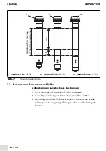
Page 11: ... ABIPLAS CUT MT 70 110 150 an der Maschine erfolgt durch eine Halterung Der Maschinenschneidbrenner wird über eine Klemmhülse auf dem gekennzeichneten Spannbereich SB1 geklemmt Ohne Klemmhülse kann die Klemmung auf SB2 erfolgen siehe Abb 7 auf Seite DE 18 1 Brennerrundführungs Set klein 2 Brennerrundführungs Set groß Abb 2 Brennerrundführung 1 2 ABIPLAS CUT 70 ABIPLAS CUT 110 und 150 Abb 3 Halteru...

Page 12: ...Kühlung Dadurch erhöht sich der Verschleiß von Isolator Elektrode und Drallring bis zur Zerstörung des Brennerkörpers Ein verschlissener Spritzerschutz ist bei Bedarf zu wechseln HINWEIS Achten Sie immer auf festen Sitz und sauberen Zustand der Schutzkappe und aller Verschleißteile Die Verschleißteile des Handschneidbrenners sind mit denen des Maschinenschneidbrenners identisch Die Plasma Schneidb...

Page 13: ...htwerte gelten WARNUNG Bei der geteilten Schutzkappe bilden Kappenkörper und Spritzerschutz eine Funktionseinheit Aus sicherheitstechnischen Gründen darf der Plasma Schneidbrenner mit dem Kappenkörper ohne Spritzerschutz nicht verwendet werden Bei Nichtbeachtung können Schäden an Personen und Maschine entstehen Bei Verschleißteilwechsel ist in jedem Fall die Plasmastromquelle auszuschalten VORSICH...

Page 14: ...0 9 30 lang 1 1 30 50 Kreuznut 0 9 30 Kreuznut 1 1 30 60 Kreuznut lang 0 9 30 ABIPLAS CUT 110 MT 110 Standard 1 0 30 50 Standard 1 2 40 70 Standard 1 4 70 90 Standard 1 6 90 110 lang 1 2 50 Kreuznut lang 1 2 50 Fugenhobeln 2 6 ABIPLAS CUT 150 MT 150 Standard 1 2 70 Standard 1 5 70 90 Standard 1 6 90 120 Standard 1 8 120 150 Kreuznut lang 1 2 50 Fugenhobeln 3 0 Tab 10 Richtwerte ...

Page 15: ... 1 2 50 70A 8 Düse Kreuznut D 0 9 30A Düse Kreuznut D 1 1 30 60A 9 Kappenkörper 10 Spritzerschutz 11 Kronendüse lang 12 Fasendüse 13 Distanzfeder 14 Lochstechkappe 15 Schutzkappe 16 Düse lang D 0 9 30A Düse lang D 1 1 30 50A 17 Düse Kreuznut lang D 0 9 30A 18 Elektrode lang 19 Isolator 20 O Ring Abb 4 Übersicht ABIPLAS CUT 70 2 3 4 5 6 7 8 9 10 11 12 13 14 15 16 17 18 19 20 1 ...

Page 16: ...se D 1 2 40 70A Düse D 1 4 70 90A Düse D 1 6 90 110A 8 Düse zum Fugenhobeln 9 Kappenkörper 10 Spritzerschutz 11 Lochstechkappe 12 Spritzerschutz 13 Distanzfeder 14 Fasendüse 15 Schutzkappe 16 Düse lang D 1 2 50A 17 Düse Kreuznut lang D 1 2 50A 18 Elektrode lang 19 Isolator 20 O Ring Abb 5 Übersicht ABIPLAS CUT 110 2 1 4 5 6 7 9 10 11 8 3 15 14 13 12 16 17 18 19 20 ...

Page 17: ...1 2 70A Düse D 1 5 70 90A Düse D 1 6 90 120A Düse D 1 8 120 150A 8 Düse zum Fugenhobeln 9 Kappenkörper 10 Spritzerschutz 11 Lochstechkappe 12 Spritzerschutz 13 Distanzfeder 14 Fasendüse 15 Schutzkappe 16 Düse Kreuznut lang D 1 2 50A 17 Elektrode lang 18 Isolator 19 O Ring Abb 6 Übersicht ABIPLAS CUT 150 2 1 3 4 5 6 7 8 9 10 11 12 13 14 15 16 17 18 19 ...

Page 18: ...f richtige Zuordnung und festen Sitz der Anschlüsse achten 3 Den richtigen Luftdruck Fließdruck einstellen sowie auf die richtige Luftmenge achten Zu geringe Luftmengen führen zur Überhitzung des Brenners 1 ABIPLAS CUT MT 70 2 ABIPLAS CUT MT 110 3 ABIPLAS CUT MT 150 Abb 7 Übersicht Spannbereich Spannbereich der Halterung für Maschinenschneidbrenner SB1 SB2 2 1 3 ...

Page 19: ...asmastromquelle muss der EN 60974 10 entsprechen Die Plasmastromquelle muss zusätzlich der EN 60974 1 entsprechen In der Zündart Kontakt oder HF sowie der Ausgangsleistung Bemessungsstrom und entsprechende Einschaltdauer müssen die Plasmastromquelle und der Schneidbrenner übereinstimmen Tab 3 auf Seite DE 4 HINWEIS Genaue Druck und Luftmengeneinstellungen sind wichtig für Das Zünden des Pilotlicht...

Page 20: ...iderate Luftdurchsatz bei 5 0 bar Fließdruck ABIPLAS CUT 70 180 l min Luftdurchsatz bei 5 0 bar Fließdruck ABIPLAS CUT 110 220 l min Luftdurchsatz bei 5 0 bar Fließdruck ABIPLAS CUT 150 280 l min Tab 4 auf Seite DE 5 HINWEIS Beachten und prüfen Sie die Sicherheitsabschaltung in Abhängigkeit der Maschinenkonfiguration Achtung Unbedingt Anlage extern schalten HINWEIS Die Plasma Schneidbrenner mit Ze...

Page 21: ...n HINWEIS Beim Betätigen des Tasters am Handbrenner und nach einer Gasvorströmzeit wird der Plasmapilotlichtbogen durch Hochfrequenzimpulse gezündet Beim Starten des Startlichtbogens mit Softstarteinrichtung darf die Schneiddüse das Werkstück nicht berühren Ein Aufsetzen der Schneiddüse auf das Werkstück führt zur Störung des Softstartregimes Verwenden Sie die Zubehörelemente für einen optimalen S...

Page 22: ...ndung der Augen Der durch das Schweißen erzeugte Lichtbogen kann Augen schädigen Schutzkleidung bzw Augenschutz tragen HINWEIS Die Bedienung der ABIPLAS CUT Schweißbrenner ist ausschließlich Fachkräften vorbehalten Da die ABIPLAS CUT Schweißbrenner in ein Schweißsystem eingebunden sind müssen Sie im Betrieb die Betriebsanleitungen der schweißtechnischen Komponenten z B Robotersteuerung beachten Üb...

Page 23: ...zkappe für eine sichere Kontaktierung ggf austauschen Im Reparaturfall bietet ABICOR BINZEL Werksreparaturen an 10 Störungen und deren Behebung GEFAHR Stromschlag Gefährliche Spannung durch fehlerhafte Kabel Überprüfen Sie alle spannungsführenden Kabel und Verbindungen auf ordnungsgemäße Installation Tauschen Sie schadhafte deformierte oder verschlissene Teile aus HINWEIS Wartungs und Reinigungsar...

Page 24: ...tgeschwindigkeit Ausrüstteile verschlissen oder beschädigt nicht angepasste Leistungsstufe Schnittgeschwindigkeit anpassen Ausrüstteile erneuern Leistungsstufe anpassen Ausgebrannte Schneiddüse beschädigte oder lose Düse Werkstückkontakt zu schneller Schnittbeginn an Werkstückkante zu starke Spritzer beim Lochstechen Pilotlichtbogen zu lange und zu oft in der Luft gezündet Pilotlichtbogen zu stark...

Page 25: ...ten Kunststoffe sind gekennzeichnet so dass eine Sortierung und Fraktionierung der Materialien zum späteren Recycling vorbereitet ist 12 2 Betriebsmittel Öle Schmierfette und Reinigungsmittel dürfen nicht den Boden belasten und in die Kanalisation gelangen Diese Stoffe müssen in geeigneten Behältern aufbewahrt transportiert und entsorgt werden Beachten Sie dabei die entsprechenden örtlichen Bestim...

Page 26: ...12 Entsorgung ABIPLAS CUT 12 3 Verpackungen ABICOR BINZEL hat die Transportverpackung auf das Notwendigste reduziert Bei der Auswahl der Verpackungsmaterialien wird auf eine mögliche Wiederverwertung geachtet ...

Page 27: ...DE 27 ABIPLAS CUT 12 Entsorgung ...

Page 28: ...ification EN 7 3 2 Emergency information EN 7 4 Scope of delivery EN 8 4 1 Transport EN 8 4 2 Storage EN 8 5 Function EN 8 6 Putting into operation EN 9 6 1 Equipping the manual cutting torch ABIPLAS CUT EN 9 6 1 1 Cutting torch body EN 9 6 1 2 Handle EN 10 6 2 Equipping the machine cutting torch ABIPLAS CUT MT EN 10 6 2 1 Machine torch body EN 10 6 2 2 Cable assembly EN 10 6 2 3 Accessories EN 10...

Page 29: ...ic safety and health requirements of the EC directive Any modification not agreed with us will void this declaration Legal representative of the documentation Hubert Metzger Kiesacker 7 9 35418 Alten Buseck 1 2 Responsibilities of the User Within the EEA European Economic Area the current version of the national implementation of the Framework Directive 89 391 EEC and the related individual direct...

Page 30: ...sidered contrary to the designated use Unauthorised conversions or power increase modifications are not allowed 2 3 Technical Data Cutting 10 C to 40 C Transport and storage 25 C to 55 C Relative humidity up to 90 at 20 C Tab 2 Ambient conditions Type ABIPLAS CUT 70 110 150 MT 70 MT 110 MT 150 Type of use manual automatic Type of voltage DC direct voltage Operating mode Single gas torch Voltage ra...

Page 31: ... max 27A 15 27A max 29A Rated current and corresponding duty cycle 70A 60 50A 100 110A 60 90A 100 150A 60 120A 100 Type of gas Compressed air Gas flow rate approx 155 l min approx 180 l min approx 235 l min Operating pressure flow pressure Torch inlet pressure bar 5 5 5 Air flow rate measured with nozzle bore 1 1 mm with nozzle bore 1 4 mm with nozzle bore 1 8 mm Plasma air l min approx 22 approx ...

Page 32: ...inless steel 18 max 25 at 70A 30 max 35 at 110A 40 max 45 at 150A 13 max 15 at 50A 25 max 30 at 90A 30 max 40 at 120A Aluminium 15 max 20 at 70A 25 max 30 at 110A 35 max 40 at 150A 8 max 10 at 50A 20 max 25 at 90A 25 max 35 at 120A Tab 5 Standard values for cutting capacity Execution Direct connector or central connector Standard length 6 m other lengths available on request Connection power air c...

Page 33: ...case of emergency immediately interrupt the following supplies Electricity gas Further measures can be found in the Power source operating instructions or in the documentation of further peripheral devices DANGER Describes imminent threatening danger If this danger is not avoided fatal or extremely critical injuries will be the result WARNING Describes a potentially dangerous situation If not avoi...

Page 34: ... accelerated in the nozzle and directed to the work piece The working arc is struck between the cutting torch electrode and the work piece The work piece material is melted by the energy of impact dissociation and ionisation and blown out by the kinetic energy of the plasma jet The compressed air is used to cool the cable assembly and cutting torch Cutting torch body type as ordered Handle Cable a...

Page 35: ...ed simply by inserting them or screwing them in For protection of the operator the screw on protection cap is equipped with a safety switch off which upon disconnection of the protection cap will automatically interrupt the switch on circuit Accessories such as torch carriage NOTE In the case of a split protection cap the cap body and spatter protector make up one functional unit CAUTION For safet...

Page 36: ...protection of the operator the screw on protection cap is equipped with a safety switch off which upon disconnection of the protection cap will automatically interrupt the switch on circuit 6 2 1 Machine torch body The machine torch body and the handle tube are designed as a cylinder In combination with the mount the machine torch can be fastened to an automatic guide or carriage 6 2 2 Cable assem...

Page 37: ... absence of a clamping sleeve it can be clamped to SB2 see Fig 7 on page EN 17 7 Operation 7 1 Equipping the torch body 1 Torch circular circular guide set small 2 Torch circular guide set large Fig 2 Torch circular guide 1 2 ABIPLAS CUT 70 ABIPLAS CUT 110 and 150 Fig 3 Mount for machine cutting torch WARNING In the case of a split protection cap the cap body and spatter protector make up one func...

Page 38: ...l cutting torch are identical to those of the machine cutting torch The plasma cutting torches are equipped with a safety switch off for protection of the operator This automatically interrupts the switch on circuit when the protection cap is removed Two spring mounted contacts are actuated when the protection cap is screwed on If the spring action of the contact pins is obstructed the existing sa...

Page 39: ...ead damage NOTE Ensure correct position The air holes should always be toward the electrode tip Type Plasma nozzle ø mm Current intensity A ABIPLAS CUT 70 MT 70 Standard 0 9 30 Standard 1 1 30 60 Standard 1 2 50 70 long 0 9 30 long 1 1 30 50 Cross slot 0 9 30 Cross slot 1 1 30 60 Long cross slot 0 9 30 ABIPLAS CUT 110 MT 110 Standard 1 0 30 50 Standard 1 2 40 70 Standard 1 4 70 90 Standard 1 6 90 ...

Page 40: ...irl ring ABIPLAS CUT 70 6 Electrode 7 Nozzle dia 0 9 30A Nozzle dia 1 1 30 60A Nozzle dia 1 2 50 70A 8 Nozzle cross slot dia 0 9 30A Nozzle cross slot dia 1 1 30 60A 9 Cap body 10 Spatter protector 11 Crown nozzle long 12 Bevel nozzle 13 Distance spring 14 Hole piercing cap 15 Protection cap 16 Nozzle long dia 0 9 30A Nozzle long dia 1 1 30 50A 17 Nozzle cross slot long dia 0 9 30A 18 Electrode lo...

Page 41: ...0 70A Nozzle dia 1 4 70 90A Nozzle dia 1 6 90 110A 8 Nozzle for gouging 9 Cap body 10 Spatter protector 11 Hole piercing cap 12 Spatter protector 13 Distance spring 14 Bevel nozzle 15 Protection cap 16 Nozzle long dia 1 2 50A 17 Nozzle cross slot long dia 1 2 50A 18 Electrode long 19 Insulator 20 O ring Fig 5 Overview ABIPLAS CUT 110 2 1 4 5 6 7 9 10 11 8 3 15 14 13 12 16 17 18 19 20 ...

Page 42: ...zle dia 1 5 70 90A Nozzle dia 1 6 90 120A Nozzle dia 1 8 120 150A 8 Nozzle for gouging 9 Cap body 10 Spatter protector 11 Hole piercing cap 12 Spatter protector 13 Distance spring 14 Bevel nozzle 15 Protection cap 16 Nozzle cross slot long dia 1 2 50A 17 Electrode long 18 Insulator 19 O ring Fig 6 Overview ABIPLAS CUT 150 2 1 3 4 5 6 7 8 9 10 11 12 13 14 15 16 17 18 19 ...

Page 43: ...r 2 Ensure that the connections are properly assigned and tightened 3 Ensure that the correct air pressure flow pressure and correct air volume are set Insufficient air volumes can lead to torch overheating 1 ABIPLAS CUT MT 70 2 ABIPLAS CUT MT 110 3 ABIPLAS CUT MT 150 Fig 7 Overview of clamping range SB1 SB2 2 1 3 Clamping range of the mount for machine cutting torch ...

Page 44: ...ion with the plasma power source must conform to EN 60974 10 The plasma power source must also be conform to EN 60974 1 The type of ignition contact or HF and the output power rated current and corresponding duty cycle of the plasma power source and of the cutting torch must be identical Tab 3 on page EN 4 NOTE Precise adjustment of the compressed air pressure and flow volume are important for ign...

Page 45: ...ion rate Air throughput at a flow pressure of 5 0 bar ABIPLAS CUT 70 180 l min Air throughput at a flow pressure of 5 0 bar ABIPLAS CUT110 220 l min Air throughput at a flow pressure of 5 0 bar ABIPLAS CUT150 280 l min Tab 4 on page EN 5 NOTE Observe and check the safety switch off depending on the machine configuration Caution Always switch system externally NOTE The plasma cutting torches with c...

Page 46: ... pilot arc via the soft start device the cutting nozzle must not touch the work piece Contact between the cutting nozzle and the work piece leads to malfunction of the soft start control Use the accessories for optimum cutting nozzle distance from the work piece The cutting arc is ignited on the work piece The cutting jet is interrupted when contact to the work piece is discontinued or the control...

Page 47: ...ed into a welding system the operating instructions of the welding components such as the robot control system must be observed during operation Check the actual gas flow at the measuring instruments or by closing and opening the corresponding gas outlet openings at the torch DANGER Risk of injury due to unexpected start up For the entire duration of maintenance servicing dismounting and repair wo...

Page 48: ...ry ABICOR BINZEL offers repair services at the factory 10 Troubleshooting NOTE Maintenance and cleaning work may only be carried out by qualified and trained specialists Always wear your personal protective clothing when performing maintenance and cleaning work NOTE If the measures described below are not successful please consult your dealer or the manufacturer Please observe the operating instru...

Page 49: ...act with work piece Start of cut at edge of work piece too fast Too much spatter when punching holes Pilot arc struck too long and too frequently in air Pilot arc too strong depending on power source Tighten nozzle or protection cap hand tight or replace nozzle if necessary Avoid contact Start cut at a lower rate Shorten avoid ignitions in air if possible Set pilot arc current to lowest possible v...

Page 50: ...Oil grease and cleaning agents must not contaminate the ground or enter sewage systems These materials must be stored transported and disposed of in suitable containers Observe the relevant local regulations and disposal instructions of the safety data sheets specified by the manufacturer of the consumables Contaminated cleaning tools brushes rags etc must also be disposed of in accordance with th...

Page 51: ...EN 25 ABIPLAS CUT 12 Disposal ...

Page 52: ...rnant le cas d urgence FR 8 4 Matériel fourni FR 8 4 1 Transport FR 8 4 2 Stockage FR 9 5 Fonctionnement FR 9 6 Mise en service FR 9 6 1 Équiper la torche de coupage manuelle ABIPLAS CUT FR 10 6 1 1 Corps de torche de coupage FR 10 6 1 2 Poignée FR 10 6 2 Équiper la torche de coupage automatique ABIPLAS CUT MT FR 10 6 2 1 Corps de la torche automatique FR 10 6 2 2 Faisceau FR 11 6 2 3 Accessoires ...

Page 53: ...ous disposons est conforme aux exigences de sécurité et de santé correspondantes Cette déclaration perd sa validité en cas de modifications non convenues avec nous Responsable de la documentation Hubert Metzger Kiesacker 7 9 D 35418 Alten Buseck 1 2 Obligation de l exploitant Dans la CEE espace économique européen l application nationale de la directive cadre 89 391 CEE ainsi que les directives in...

Page 54: ...ions Toute autre utilisation que celle décrite dans la section Utilisation conforme aux dispositions est considérée comme non conforme Des transformations ou modifications servant à augmenter la puissance du produit sont interdites 2 3 Caractéristiques techniques Coupage 10 C à 40 C Transport et stockage 25 C à 55 C Humidité de l air relative jusqu à 90 à 20 C Tab 2 Conditions ambiantes Type ABIPL...

Page 55: ... marche respectif 70A 60 50A 100 110A 60 90A 100 150A 60 120A 100 Type de gaz air comprimé Débit de gaz env 155 l min env 180 l min env 235 l min Pression de service pression d écoulement Pression d entrée bar 5 5 5 Débit d air mesuré pour une tuyère 1 1 mm une tuyère 1 4 mm une tuyère 1 8 mm Air plasma l min env 22 env 30 env 39 Air softstart l min 12 15 15 Durée de post gaz s 60 Choix de la tuyè...

Page 56: ...oxydable 18 max 25 jusqu à 70A 30 max 35 jusqu à 110A 40 max 45 jusqu à 150A 13 max 15 jusqu à 50A 25 max 30 jusqu à 90A 30 max 40 jusqu à 120A Aluminium 15 max 20 jusqu à 70A 25 max 30 jusqu à 110A 35 max 40 jusqu à 150A 8 max 10 jusqu à 50A 20 max 25 jusqu à 90A 25 max 35 jusqu à 120A Tab 5 Valeurs approximatives pour la capacité de coupe Type de raccord Raccord vissé ou centralisé Longueur stan...

Page 57: ...cation Les consignes d avertissement utilisées dans ce mode d emploi sont divisées en quatre niveaux différents et les travaux spécifiques sont marqués par ces consignes placées en tête En fonction de leur importance elles ont la signification suivante 1 Plaque signalétique sur la face arrière 2 Autocollant ABICOR BINZEL Fig 1 Plaque signalétique A B I C O R BINZEL ABIPLAS110 1 2 DANGER Signale un...

Page 58: ... 4 2 Stockage Conditions physiques lors du stockage en lieu clos Voir Tab 2 Conditions ambiantes Page FR 4 REMARQUE Signale le risque d obtenir un résultat de travail non satisfaisant et de dommages matériels Corps de torche de coupage type selon la commande Poignée Faisceau Mode d emploi Tab 8 Matériel fourni Contrôle à la réception Contrôlez à l aide du bon de livraison si la livraison est compl...

Page 59: ... matériaux faiblement et fortement alliées à l air comprimé en milieu industriel et commercial Elles ne doivent être utilisées que par un personnel qualifié Ces torches plasma sont des torches de coupage refroidies par air REMARQUE Dans le cas du montage de la coiffe de protection séparée le corps de coiffe et l isolant de buse forment une unité fonctionnelle ATTENTION Pour des raisons de sécurité...

Page 60: ... marche involontaire lorsque la torche de coupage est déposée 6 2 Équiper la torche de coupage automatique ABIPLAS CUT MT Les torches de coupage automatiques ABIPLAS CUT MT existent en trois niveaux de puissance 70A 110A et 150A avec un facteur de marche de 60 ED Les buses de torches de coupage et l axe du corps de torche sont disposés en ligne droite Les pièces d usure tuyère plasma coiffe de pro...

Page 61: ... coupage automatique La fixation des torches de coupage automatiques ABIPLAS CUT MT 70 110 150 sur la machine se fait par l intermédiaire d un support La torche de coupage est fixée par une patte de fixation sur la zone de serrage désignée SB1 Sans patte de fixation le serrage peut se faire sur SB2 Voir Fig 7 Page FR 18 REMARQUE Veillez à ne pas déformer la coiffe de protection et endommager le ta...

Page 62: ... refroidissement Ceci entraîne l usure de l isolant de l électrode et de la bague diffuseur jusqu à la destruction du corps de torche Un isolant de buse usé doit être remplacé au besoin REMARQUE Veillez toujours à la propreté et au bon serrage de la coiffe de protection et de toutes les pièces d usure Les pièces d usure de la torche de coupage manuelle sont identiques à celles de la torche de coup...

Page 63: ...e coiffe et l isolant de buse forment une unité fonctionnelle Pour des raisons de sécurité il est interdit d utiliser la torche de coupage plasma avec le corps de coiffe sans isolant de buse Tout non respect peut entraîner de dommages corporels et des dommages sur la machine Lors du remplacement des pièces d usure la source de courant plasma doit être coupée dans tous les cas ATTENTION Un vissage ...

Page 64: ...0 50 Rainure en croix 0 9 30 Rainure en croix 1 1 30 60 Rainure en croix longue 0 9 30 ABIPLAS CUT 110 MT 110 Standard 1 0 30 50 Standard 1 2 40 70 Standard 1 4 70 90 Standard 1 6 90 110 Longue 1 2 50 Rainure en croix longue 1 2 50 Gougeage 2 6 ABIPLAS CUT 150 MT 150 Standard 1 2 70 Standard 1 5 70 90 Standard 1 6 90 120 Standard 1 8 120 150 Rainure en croix longue 1 2 50 Gougeage 3 0 Tab 10 Valeu...

Page 65: ...ainure en croix D 0 9 30A Buse rainure en croix D 1 1 30 60A 9 Corps de coiffe 10 Isolant de buse 11 Buse couronne longue 12 Buse à chanfrein 13 Patin fil 14 Patin à créneaux 15 Coiffe de protection 16 Buse longue D 0 9 30A Buse longue D 1 1 30 50A 17 Buse rainure en croix longue D 0 9 30A 18 Électrode longue 19 Isolant 20 Joint torique Fig 4 Aperçu ABIPLAS CUT 70 2 3 4 5 6 7 8 9 10 11 12 13 14 15...

Page 66: ...70A Buse D 1 4 70 90A Buse D 1 6 90 110A 8 Buse pour le gougeage 9 Corps de coiffe 10 Isolant de buse 11 Patin à créneaux 12 Isolant de buse 13 Patin fil 14 Buse à chanfrein 15 Coiffe de protection 16 Buse longue D 1 2 50A 17 Buse rainure en croix longue D 1 2 50A 18 Électrode longue 19 Isolant 20 Joint torique Fig 5 Aperçu ABIPLAS CUT 110 2 1 4 5 6 7 9 10 11 8 3 15 14 13 12 16 17 18 19 20 ...

Page 67: ...e D 1 5 70 90A Buse D 1 6 90 120A Buse D 1 8 120 150A 8 Buse pour le gougeage 9 Corps de coiffe 10 Isolant de buse 11 Patin à créneaux 12 Isolant de buse 13 Patin fil 14 Buse à chanfrein 15 Coiffe de protection 16 Buse rainure en croix longue D 1 2 50A 17 Électrode longue 18 Isolant 19 Joint torique Fig 6 Aperçu ABIPLAS CUT 150 2 1 3 4 5 6 7 8 9 10 11 12 13 14 15 16 17 18 19 ...

Page 68: ...pureté 2 Veiller à la disposition correcte et au bon serrage des raccordements 3 Régler la pression d air pression d écoulement veiller au débit d air correct Un débit trop faible entraîne la surchauffe de la torche 1 ABIPLAS CUT MT 70 2 ABIPLAS CUT MT 110 3 ABIPLAS CUT MT 150 Fig 7 Aperçu zone de serrage SB1 SB2 2 1 3 Zone de serrage du support pour torche de coupage automatique ...

Page 69: ...née à la source de courant plasma doit être conforme à la norme EN 60974 10 La source de courant plasma doit également correspondre à la norme EN 60974 1 Dans l amorçage contact ou HF de même que dans la puissance de sortie courant assigné et le facteur de marche respectif la source de courant plasma et la torche de coupage doivent correspondre Tab 3 Page FR 4 REMARQUE Le réglage exact de la press...

Page 70: ...uile de 99 99 Débit d air à une pression de 5 0 bars ABIPLAS CUT 70 180 l min Débit d air à une pression de 5 0 bars ABIPLAS CUT 110 220 l min Débit d air à une pression de 5 0 bars ABIPLAS CUT 150 280 l min Tab 4 Page FR 5 REMARQUE Observez et contrôlez le système de sécurité en fonction de la configuration de machine Attention Assurer un pilotage externe du système REMARQUE Les torches de coupag...

Page 71: ...le bouton est actionné sur la torche manuelle et après une temporisation de pré gaz l arc pilote plasma est amorcé par impulsion de haute fréquence Veiller à ce que la tuyère ne soit pas en contact avec la pièce lors de l amorçage de l arc pilote avec équipement softstart Un contact de la tuyère avec la pièce d œuvre provoque un disfonctionnement du softstart Utilisez les accessoires afin d obteni...

Page 72: ...s yeux L arc créé lors du soudage peut entraîner des lésions oculaires Porter des vêtements et des lunettes de protection REMARQUE La torche de soudage ABIPLAS CUT doit être utilisée uniquement par un personnel qualifié Lorsque la torche de soudage ABIPLAS CUT est intégrée dans un système de soudage vous devez respecter lors de l utilisation le mode d emploi de chaque élément de l installation par...

Page 73: ... contact de la coiffe de protection et le cas échéant remplacez la afin d obtenir un contact sûr Les réparations peuvent être effectuées par ABICOR BINZEL 10 Dépannage DANGER Risque d électrocution Tension dangereuse en raison des câbles endommagés Veillez à ce que tous les câbles et raccordements sous tension soient correctement installés Remplacez des pièces endommagées déformées ou usées REMARQ...

Page 74: ...e la distance de la torche Utiliser une faible épaisseur de la matière Adapter le niveau de puissance Forte formation de barbe Vitesse de coupe trop faible ou trop élevée Pièces d équipement usées ou endommagées Niveau de puissance non adapté Adapter la vitesse de coupe Remplacer les pièces d équipement Adapter le niveau de puissance Tuyère détruite par le feu Tuyère détériorée ou mal montée Conta...

Page 75: ...t ainsi réutilisables pratiquement sans restrictions Les matières plastiques sont marquées afin de permettre un classement et une séparation des matériaux pour un recyclage ultérieur Electrode détruite par le feu Perte de pression en cours de coupe liée à un mauvais réglage du manostat Electrode mal montée Arc pilote amorcé trop longtemps ou trop souvent hors masse Corriger le réglage du manostat ...

Page 76: ...sujet les prescriptions locales correspondantes et les indications figurant dans les fiches de données de sécurité du fabricant de ces produits concernant l élimination Les outils de nettoyage contaminés pinceau chiffon etc doivent être également éliminés selon les indications du fabricant des produits consommables 12 3 Emballages ABICOR BINZEL a réduit l emballage de transport au nécessaire Lors ...

Page 77: ...FR 27 ABIPLAS CUT 12 Elimination ...

Page 78: ... 4 1 Transporte ES 8 4 2 Almacenamiento ES 8 5 Función ES 8 6 Puesta en servicio ES 9 6 1 Equipar la antorcha de corte manual ABIPLAS CUT ES 9 6 1 1 Cuerpo de antorcha de corte ES 9 6 1 2 Empuñadura ES 10 6 2 Equipar la antorcha de corte automático ABIPLAS CUT MT ES 10 6 2 1 Cuerpo de antorcha de corte automático ES 10 6 2 2 Conjunto de cables ES 10 6 2 3 Accesorios ES 10 7 Operación ES 12 7 1 Equ...

Page 79: ...ierde su validez ante una modificación que no haya sido coordinada con nosotros Responsable de la documentación Hubert Metzger Kiesacker 7 9 D 35418 Alten Buseck 1 2 Responsabilidad del usuario En el AEE Área Económica Europea debe observarse y cumplirse a nivel nacional con la Directiva marco 89 391 CEE así como con las correspondientes directivas individuales y de éstas en particular la Directiv...

Page 80: ...nsidera como no conforme a lo prescrito Cualquier modificación no autorizada o el incrementar las capacidades propias del equipo no están permitidas 2 3 Datos técnicos Corte 10 C a 40 C Transporte y almacenamiento 25 C a 55 C Humedad relativa del aire hasta 90 a 20 C Tab 2 Condiciones ambientales Tipo ABIPLAS CUT 70 110 150 MT 70 MT 110 MT 150 Tipo de guiado Manual Automático Tipo de tensión Corri...

Page 81: ...inal y ciclo de trabajo respectivo 70 A 60 50 A 100 110 A 60 90 A 100 150 A 60 120 A 100 Tipo de gas Aire comprimido Flujo de gas aprox 155 l min aprox 180 l min aprox 235 l min Presión de trabajo presión de flujo Presión de entrada a la antorcha bar 5 5 5 Diámetro del orificio de descarga Orificio de tobera 1 1 mm Orificio de tobera 1 4 mm Orificio de tobera 1 8 mm Aire de plasma l min aprox 22 a...

Page 82: ...máx 45 con 150A 13 máx 15 con 50A 25 máx 30 con 90A 30 máx 40 con 120A Aluminio 15 máx 20 con 70 A 25 máx 30 con 110A 35 máx 40 con 150A 8 máx 10 con 50A 20 máx 25 con 90A 25 máx 35 con 120A Tab 5 Valores orientativos para la capacidad de corte Modelo Conector directo o central Longitud estándar 6 m otras longitudes disponibles bajo pedido Conexión de cable de corriente de aire G1 4 Tab 6 Conjunto...

Page 83: ... según importancia decreciente significan lo siguiente 3 2 Indicaciones para emergencias En caso de emergencia interrumpir inmediatamente los siguientes suministros Corriente gas Para más medidas leer el manual de instrucciones Fuente de corriente o la documentación de otros aparatos periféricos PELIGRO Indica un peligro inminente Si no se evita las consecuencias son la muerte o lesiones muy grave...

Page 84: ...anque genera arco plasma conductivo el cual se acelera en la tobera y es conducido a la pieza de trabajo El arco de trabajo se enciende entre el electrodo de la antorcha de corte y la pieza de trabajo El material de la pieza de trabajo se recarga por fusión a través de la energía del impacto de la disociación y de la ionización La energía cinética de la Cuerpo de antorcha de corte tipo según pedid...

Page 85: ... está colocada en un ángulo de 110 en relación al eje de la empuñadura Las piezas de repuesto como por ejemplo tobera plasma tapón de protección anillo rotatorio electrodo y aislante se recambian INDICACIÓN En el tapón de protección dividido el cuerpo del tapón y el protector contra proyecciones forman una unidad funcional CUIDADO Por razones de seguridad queda prohibido utilizar la antorcha de co...

Page 86: ... están colocados en una línea recta Las piezas de repuesto como por ejemplo tobera plasma tapón de protección anillo rotatorio electrodo y aislante se recambian fácilmente enchufándolas o atornillándolas Para la seguridad del operador el tapón de protección está dotado de una desconexión de seguridad que interrumpe automáticamente el circuito de encendido cuando se quita el tapón de protección 6 2...

Page 87: ...e corte automático se sujeta en el área de sujeción SB1 marcada mediante un casquillo de apriete Sin el casquillo de apriete puede fijarse en SB2 Véase Fig 7 en página ES 18 INDICACIÓN Prestar atención al atornillar el tornillo prisionero que no se aplaste el tapón de protección deteriorando la rosca interior 1 Juego de guía circular de antorcha pequeña 2 Juego de guía circular de antorcha grande ...

Page 88: ...se aumenta el desgaste del aislante del electrodo y del anillo rotatorio e incluso puede conducir a la destrucción del cuerpo de la antorcha Un protector contra proyecciones gastado se debe cambiar cuando sea necesario INDICACIÓN Asegurarse siempre de la posición fija y del estado limpio del tapón de protección y de todas las piezas de repuesto Las piezas de repuesto de la antorcha de corte manual...

Page 89: ... protección dividido el cuerpo del tapón y el protector contra proyecciones forman una unidad funcional Por razones de seguridad queda prohibido utilizar la antorcha de corte por plasma con el cuerpo del tapón sin protector contra proyecciones En caso de falta de observancia pueden producirse daños en personas y máquina El suministro de corriente debe estar apagado al cambiar las piezas de repuest...

Page 90: ...ga 1 1 30 50 Ranura en cruz 0 9 30 Ranura en cruz 1 1 30 60 Ranura en cruz larga 0 9 30 ABIPLAS CUT 110 MT 110 Estándar 1 0 30 50 Estándar 1 2 40 70 Estándar 1 4 70 90 Estándar 1 6 90 110 larga 1 2 50 Ranura en cruz larga 1 2 50 Biselado 2 6 ABIPLAS CUT 150 MT 150 Estándar 1 2 70 Estándar 1 5 70 90 Estándar 1 6 90 120 Estándar 1 8 120 150 Ranura en cruz larga 1 2 50 Biselado 3 0 Tab 10 Valores ind...

Page 91: ...ruz diámetro 0 9 30A Tobera ranura en cruz diámetro 1 1 30 60A 9 Cuerpo de la tapa 10 Protector contra proyecciones 11 Tobera de corona larga 12 Tobera cónica 13 Resorte espaciador 14 Capuchón perforado 15 Tapón de protección 16 Tobera larga diámetro 0 9 30A Tobera larga diámetro 1 1 30 50A 17 Tobera ranura en cruz larga diámetro 0 9 30A 18 Electrodo largo 19 Aislante 20 O ring Fig 4 Vista general...

Page 92: ...1 4 70 90A Tobera diámetro 1 6 90 110A 8 Tobera para biselado 9 Cuerpo de la tapa 10 Protector contra proyecciones 11 Capuchón perforado 12 Protector contra proyecciones 13 Resorte espaciador 14 Tobera cónica 15 Tapón de protección 16 Tobera larga diámetro 1 2 50A 17 Tobera ranura en cruz larga diámetro 1 2 50A 18 Electrodo largo 19 Aislante 20 O ring Fig 5 Vista general ABIPLAS CUT 110 2 1 4 5 6 ...

Page 93: ...Tobera diámetro 1 6 90 120A Tobera diámetro 1 8 120 150A 8 Tobera para biselado 9 Cuerpo de la tapa 10 Protector contra proyecciones 11 Capuchón perforado 12 Protector contra proyecciones 13 Resorte espaciador 14 Tobera cónica 15 Tapón de protección 16 Tobera ranura en cruz larga diámetro 1 2 50A 17 Electrodo largo 18 Aislante 19 O ring Fig 6 Vista general ABIPLAS CUT 150 2 1 3 4 5 6 7 8 9 10 11 1...

Page 94: ...as conexiones estén propiamente localizadas y apretadas 3 Asegurarse de que la presión del aire presión de flujo sea correcta y de que el flujo de aire volumen esté ajustado Un flujo de aire insuficiente puede sobrecalentar la antorcha 1 ABIPLAS CUT MT 70 2 ABIPLAS CUT MT 110 3 ABIPLAS CUT MT 150 Fig 7 Vista general del área de sujeción SB1 SB2 2 1 3 Área de sujeción del soporte para antorcha de c...

Page 95: ... por plasma debe cumplir los requisitos de la norma EN 60974 10 La fuente de corriente por plasma debe cumplir también los requisitos de la norma EN 60974 1 El tipo de encendido contacto o AF y la potencia de salida corriente nominal y ciclo de trabajo respectivo de la fuente de corriente por plasma y de la antorcha de corte deben coincidir Tab 3 en página ES 4 INDICACIÓN El ajuste exacto de presi...

Page 96: ...de un 99 99 Paso de aire con 5 0 bar de presión suministrada ABIPLAS CUT 70 180 l min Paso de aire con 5 0 bar de presión suministrada ABIPLAS CUT110 220 l min Paso de aire con 5 0 bar de presión suministrada ABIPLAS CUT150 280 l min Tab 4 en página ES 5 INDICACIÓN Verificar y controlar el interruptor automático de seguridad con respecto a la configuración de la máquina Atención Siempre conectar y...

Page 97: ...INDICACIÓN Al accionar el gatillo antorcha manual y después del preflujo de gas se enciende el arco piloto plasmático a través de impulsos de alta frecuencia Al iniciar el arco de arranque con dispositivo de arranque suave la tobera de soplete no debe estar tocando la pieza de trabajo Cuando la tobera de soplete toca la pieza de trabajo es imposible el arranque suave Utilizar los accesorios para u...

Page 98: ...métodos materiales plasma por favor consulte la documentación pertinente Esta información no se encuentra en este manual de instrucciones AVISO Deslumbramiento de los ojos El arco generado por la soldadura puede dañar los ojos Llevar ropa protectora y equipo protector para los ojos INDICACIÓN Sólo especialistas deben operar las antorchas de soldadura ABIPLAS CUT Dado que las antorchas de soldadura...

Page 99: ...ntacto del tapón de protección para garantizar un buen contacto reemplazar si fuera necesario En caso de reparaciones ABICOR BINZEL ofrece reparaciones en fábrica PELIGRO Peligro de lesiones por arranque inesperado Observar lo siguiente durante todos los trabajos de mantenimiento servicio desmontaje y reparación Desconectar la fuente de corriente Cerrar el suministro de aire comprimido Desconectar...

Page 100: ...uptor automático por caída de presión Reducir la velocidad de corte Reducir el ángulo de inclinación Utilizar un material menos grueso Cambiar los accesorios Ajustar el nivel de potencia Arco de corte se interrumpe Velocidad de corte demasiado baja Distancia de antorcha demasiado grande Material demasiado grueso Nivel de potencia insuficiente Aumentar la velocidad de corte Reducir la distancia de ...

Page 101: ... tobera si fuera necesario Evitar el contacto Comenzar el corte con velocidad baja Reducir evitar los encendidos en el aire si posible Ajustar una corriente baja para el arco piloto si posible Fuerte quemadura del electrodo Caída de presión durante el corte por ajuste incorrecto del interruptor automático por caída de presión Electrodo suelto Arco piloto encendido por largo tiempo y demasiadas vec...

Page 102: ... 12 2 Combustibles Los aceites los lubricantes y los detergentes no deben contaminar el suelo ni llegar al alcantarillado Estas sustancias deben almacenarse transportarse y eliminarse en tanques apropiados Observe en esto las correspondientes disposiciones locales y las indicaciones para la eliminación de desechos dadas en las hojas de datos de seguridad que especifica el fabricante de medios de p...

Page 103: ...ES 27 ABIPLAS CUT 12 Eliminación ...

Page 104: ...O R T H E W E L D E R S W O R L D www binzel abicor com Alexander Binzel Schweisstechnik GmbH Co KG Postfach 10 01 53 D 35331 Giessen Tel 49 0 64 08 59 0 Fax 49 0 64 08 59 191 Email info binzel abicor com BAL 0099 2012 07 10 ...

Reviews: