EN - 18
BAL.0388.0 • 2018-08-08
7 Operation
e
BOX
7 Operation
7.1 Control elements
NOTICE
• The
eBOX
may only be operated by qualified personnel (in Germany see TRBS 1203).
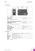
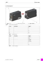
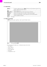
1
eBOX
status LED P1
2
Key-operated switch S1
3
Reset button S2
4
Front drive status LED P2
5
Rear drive status LED P3
6
Outlet air grille
7
Manual terminal port X10
8
Hot wire power source port X13
9
Option
10
Option
11
Control lead port
M-Drive
or
MF1
X11
12
US1/US2 port X3
(on AIDA version only)
13
I/O interface port X2
14
Inlet air grille
15
Mains cable port X1
16
Main switch Q1
17
Ethernet/USB interface
Fig. 11
eBOX
control elements
1
2
3
4
5
6
7
8
9
10
11
14
15
16
17
13
12
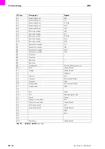
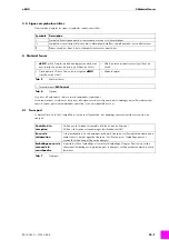
Symbol
Name
Fig.
Switching state ON (LEDs illuminated in green, device fans running)
Switching state OFF (no power to the system)
Key-operated switch S1
Switch position: automatic: the wire feeder is fully functional when the cover (
M-Drive
) is closed
Switch position: manual: the protective device is bridged. The inching (wire feed) function is enabled
when the cover (
M-Drive
) is open. The key can be removed in any position.
* Solely for systems with
M-Drive
; obsolete for other versions.
Reset button S2
Fig.
Press the button after eliminating a fault. The internal control system is reset to the starting position.
LED P3, rear drive
Fig.
Status green = ready, status red, flashing = fault
LED P2, front drive
Fig.
Status green = ready, status red, flashing = fault
I ON
O
OFF
Auto
Service

