iSTM mini
6 Commissioning
BAL.0523.0 • 2019-10-17
EN - 15
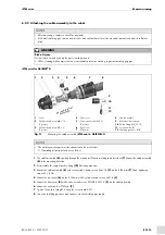
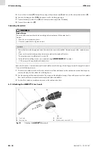
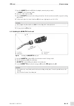
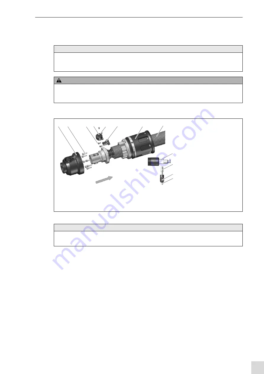
6.2.2 Attaching the cable assembly to the robot
iSTM mini for ABIROB
®
G
1
is guided through the mounted iSTM mini welding torch interface
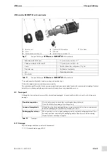
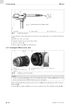
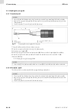
. Mount the cable assembly
in the mounting direction.
2
Disassemble the straight push-in fitting
3
Mount the cable assembly
with seven cylinder head screws M4 × 16
on the iSTM mini
. Max. tightening
torque M = 4 Nm.
4
on the iSTM mini with 2 cylinder head screws M3 × 6
.
5
with 2 countersunk screws DIN 965 M3 × 5
on the cable assembly.
6
Mount the cover on the iSTM mini
7
Tighten the push-in fitting Ø 6 using the screw-in aid AF11.
8
Insert the shielding gas hose and connect it to the shielding gas supply.
NOTICE
• After mounting is complete, check for any leaks.
• All leads (shielding gas, compressed air lines, and coolant hoses) must be mounted torsion-free and with sufficient
play.
WARNING
Risk of injury
Serious injuries may be caused by parts swirling around.
• When cleaning with compressed air, wear suitable protective clothing, in particular safety goggles.
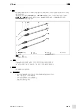
1
Cover
2
Cylinder head screw M4 × 16
(7 pieces)
3
Cylinder head screw M3 × 6
(2 pieces)
4
Front cover
5
Countersunk screw M3 × 5
(2 pieces)
6
Rear cover
7
iSTM mini
8
Cable assembly
9
Machine-side connector
10
Push-in fitting Ø 6/G1/8"
11
Screw-in aid AF11
12
Shielding gas hose Ø
6
Fig. 11
Mounting the cable assembly
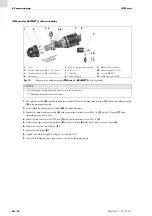
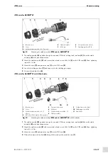
iSTM mini
for
ABIROB
®
G
NOTICE
• The welding current port must be connected to the wire feeder.
Operating instructions for the wire feeder
Mou
nting
dire
ction
1
2
3
4
5
6
7
8
9
10
11
12


