iSTM mini
6 Commissioning
BAL.0523.0 • 2019-10-17
EN - 19
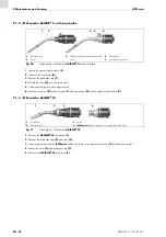
1
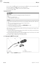
Equip the
ABIROB
®
G
torch neck
with a tip adaptor, contact tip, and gas nozzle.
ABIROB
®
350 GC instruction leaflet
2
Loosen the cylinder head screw
.
3
Mount the
ABIROB
®
G
torch neck in the welding torch interface. The torch must be inserted all the way into the welding
torch interface.
4
To fix the torch, tighten the cylinder head screw
with a max. tightening torque of M = 6 Nm.
5
Put the protective cap
back on.
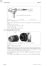
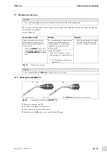
6.4 Attaching the ABIROB
®
W torch neck
1
Equip the
ABIROB
®
W
torch neck
with a tip adaptor, contact tip, and gas nozzle.
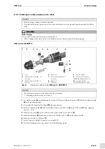
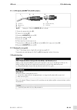
2
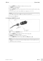
Insert the positioning pin
in the marked bore.
The
ABIROB
®
W
may be attached in this position only.
3
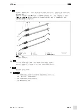
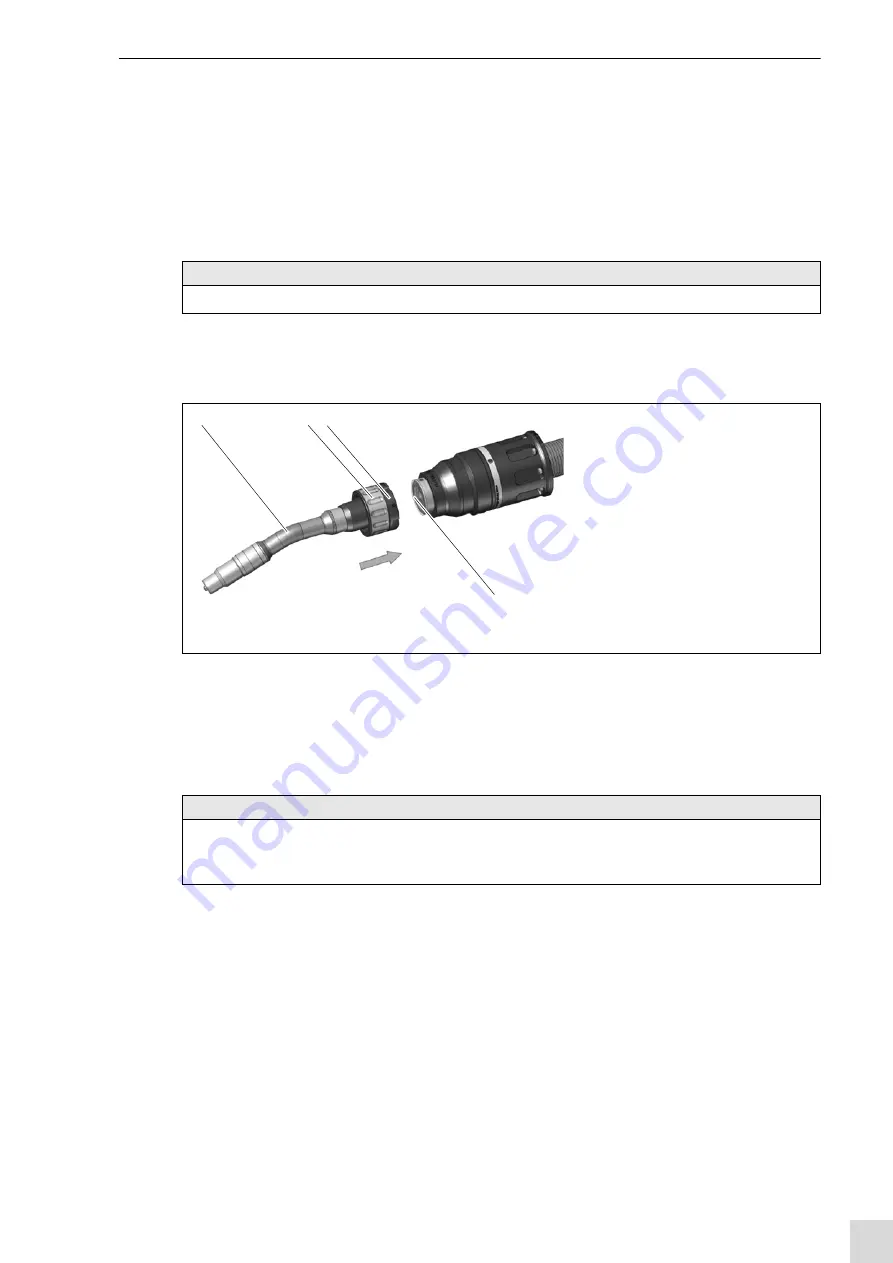
Screw the
ABIROB
®
W
torch neck with retaining nut
on to the
iSTM mini
interface
.
NOTICE
• Do not tighten the cylinder head screw
unless the welding torch is already mounted.
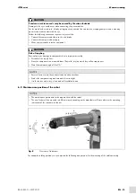
1
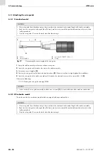
Torch neck
2
Retaining nut
3
Positioning pin
4
iSTM mini
Fig. 16
Attaching the
ABIROB
®
W
torch neck
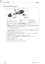
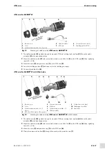
NOTICE
• After repeated use, it may not be possible to loosen the welding torch by hand. A wrench is provided to assist with
loosening.
• Do not use pliers to loosen the welding torch.
1
2
3
4
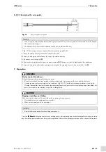
Mou
nting
dire
ction


