EN - 20
BAL.0523.0 • 2019-10-17
6 Commissioning
iSTM mini
6.5 Attaching the wire guide
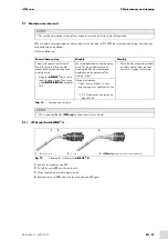
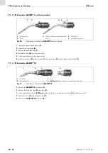
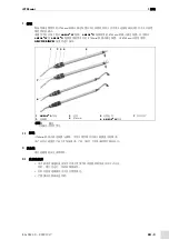
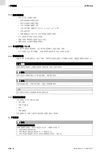
6.5.1 Standard model
1
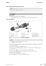
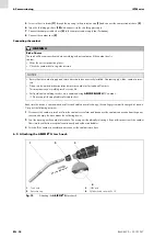
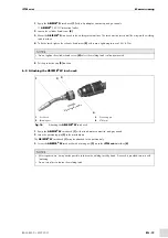
Equip the cable assembly with torch neck and wear parts.
2
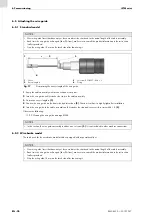
Insert the wire guide until it reaches the stop in the cable assembly.
3
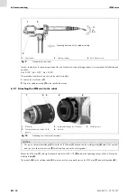
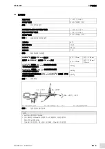
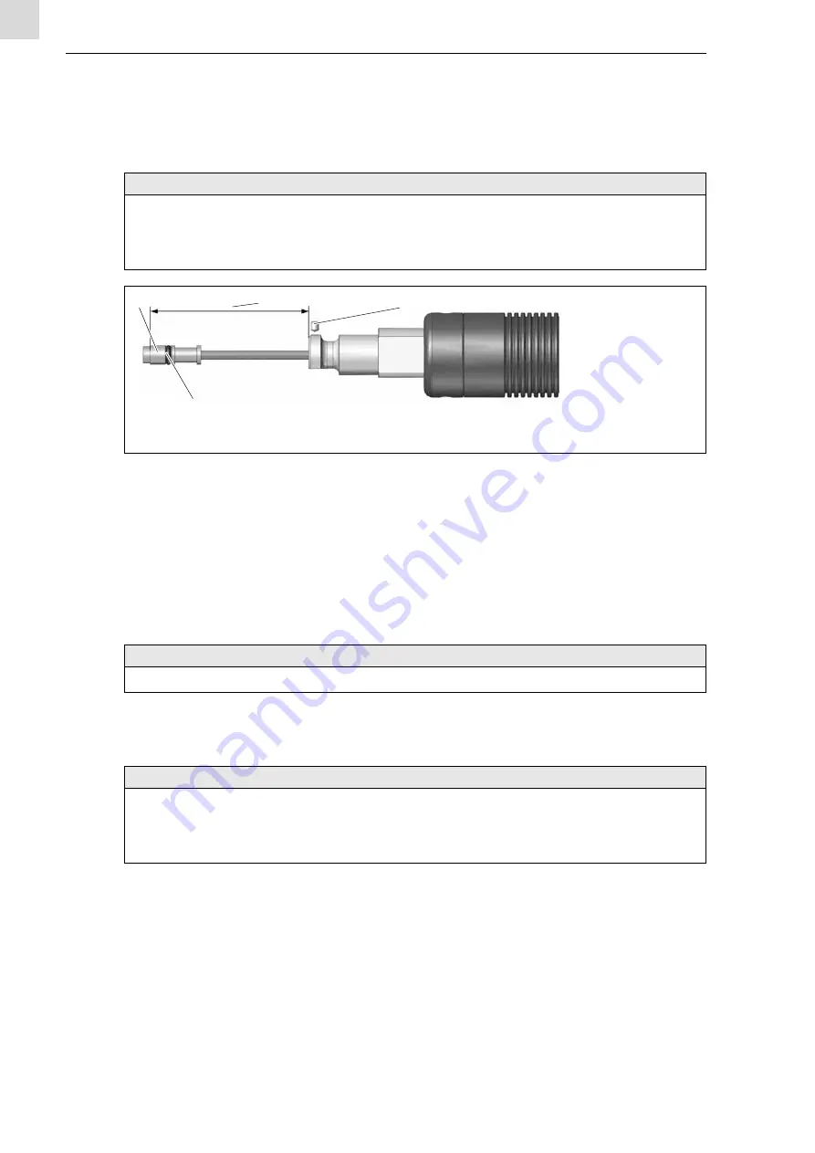
Determine excess length a
4
Shorten the wire guide on the front side by dimension a
. Shorten it so that it is slightly tight after installation.
5
Insert the wire guide in the cable assembly until it reaches the stop and secure with set screw M4 × 5
.
Observe the following:
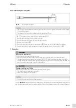
9.2 Cleaning the wire guide on page EN-25
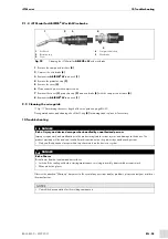
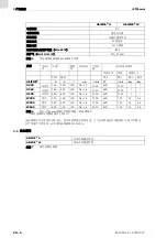
6.5.2 Wire brake model
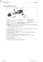
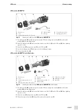
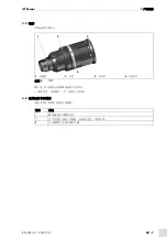
The torch neck for the wire brake model must be equipped with a special neckliner.
NOTICE
• New wire guide liners that have not yet been used must be shortened to the actual length of the cable assembly.
• Each time the wire guide is changed (liner, PA liner), make sure to consult the product information in the instruction
leaflets provided.
• Strip the wire guide 15 mm on the torch side after shortening it.
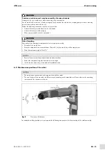
1
Sleeve
2
Excess length a
3
Set screw ISO 4027 – M4 × 5
4
O-ring
Fig. 17
Determining the excess length of the wire guide
NOTICE
• In this section, the wire guide assembly includes one set screw
. It is not included in other machine connections.
1
2
a
3
4
NOTICE
• New wire guide liners that have not yet been used must be shortened to the actual length of the cable assembly.
• Each time the wire guide is changed (liner, PA liner), make sure to consult the product information in the instruction
leaflets provided.
• Strip the wire guide 15 mm on the torch side after shortening it.


