iSTM mini
7 Operation
BAL.0523.0 • 2019-10-17
EN - 21
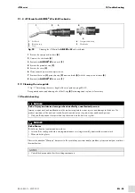
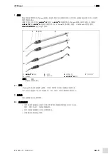
6.5.3 Shortening the wire guide
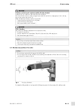
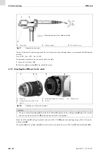
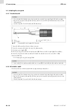
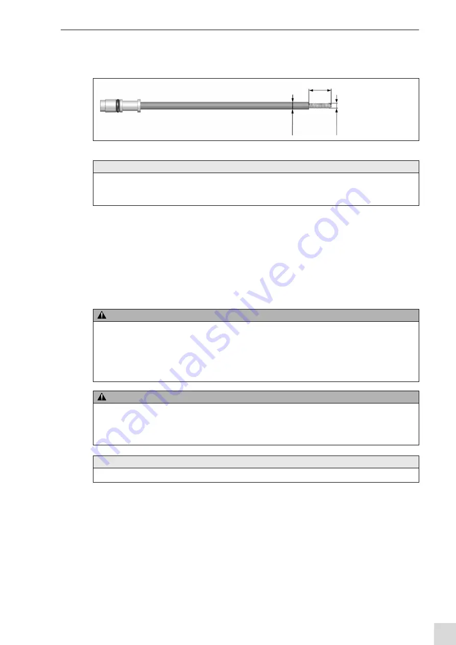
Fig. 17 Determining the excess length of the wire guide on page EN-20
1
Equip the cable assembly with torch neck and wear parts.
2
Insert the wire guide until it reaches the stop in the cable assembly.
3
Determine excess length a
4
Shorten the wire guide on the front side by dimension a
. Shorten it so that it is slightly tight after installation.
5
Insert the wire guide in the cable assembly until it reaches the stop and secure with set screw M4 × 5
.
7 Operation
Since the
iSTM mini
is integrated in the torch’s welding process, the operating steps are performed after the respective torch
and the welding power source have been put into operation. Observe the operating instructions of the relevant welding torch.
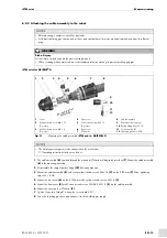
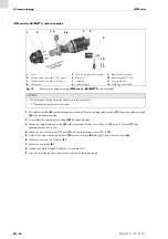
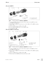
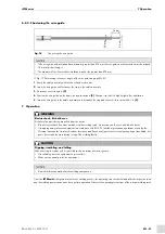
Fig. 18
Shortening the wire guide
NOTICE
• If the wire guide with insulation has a diameter greater than Ø 5 mm, the wire guide on the torch-side must be stripped
15 mm after shortening it.
• The diameter of the liner without insulation may not be greater than Ø 5 mm.
15 mm
≤5
m
m
≥5
m
m
WARNING
Electric shock. Risk of burns.
Risk of molten parts being propelled from the device.
• Risk of electric shock if contact is made with the welding torch. An arc can stun the eyes and lead to burns.
• Use appropriate protective equipment in accordance with BGV D1 (accident prevention regulations issued by the
German Institution for Statutory Accident Insurance and Prevention) to prevent electrical decoupling of touchable, live
parts. It must also be worn during setup of the welding facility.
CAUTION
Slipping, stumbling, and falling.
When entering the robot cell, it is possible to slip on scraps of wire or grease.
• Use suitable protective equipment to prevent this.
• Wear your personal protective equipment.
NOTICE
• Consult the documentation for the welding components.


